Optical isolator and laser processing system

An optical isolator and laser processing technology, which is applied in laser welding equipment, metal processing equipment, manufacturing tools, etc., can solve the problems of burning lasers, high energy density of laser beams, and decreased output power of lasers, so as to prolong service life and improve Quality, the effect of improving quality

Active Publication Date: 2015-03-18
HANS LASER TECH IND GRP CO LTD
View PDF7 Cites 10 Cited by
  • Summary
  • Abstract
  • Description
  • Claims
  • Application Information

AI Technical Summary

Problems solved by technology

[0007] In addition, when the CO2 laser is used for processing, when the high-energy CO2 laser beam irradiates those materials with low absorption rate in the 10.6μm band or materials with high surface finish, the workpiece will reflect a large amount of laser energy, and part of the reflected light will be along the The original optical path returns to the CO2 laser oscillator cavity. Due to the high energy density of the laser beam, a large amount of heat will be generated, resulting in a decrease in the output power of the laser, resulting in a decrease in the service life of the laser, and in severe cases, the laser will be burned

Method used


Image

  • Optical isolator and laser processing system
  • Optical isolator and laser processing system
  • Optical isolator and laser processing system

Examples


Embodiment Construction

[0025] In order to make the object, technical solution and advantages of the present invention clearer, the present invention will be further described in detail below in conjunction with the accompanying drawings and embodiments. It should be understood that the specific embodiments described here are only used to explain the present invention, not to limit the present invention.

[0026] The specific realization of the present invention is described in detail below in conjunction with specific embodiment:

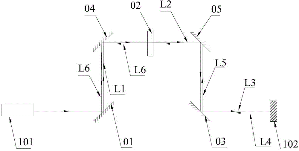
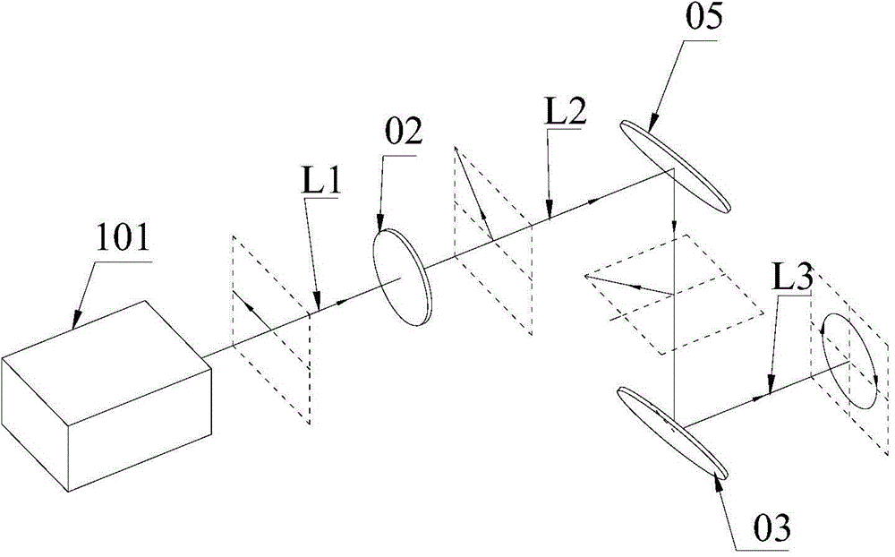
[0027] figure 2 shows the internal optical path diagram of the optical isolator of the embodiment of the present invention, image 3 A partial light path diagram of the optical isolator according to the embodiment of the present invention is shown, and for convenience of description, only parts related to this embodiment are shown.

[0028] The optical isolator is mainly used in laser processing (such as laser cutting, laser drilling, laser welding, etc.) Improve the ...


PUM


Abstract

The invention applies to the field of laser processing, and provides an optical isolator for a laser processing system. The optical isolator comprises a film absorbing reflector, a half wave plate and a 90-degree phase-shift delay mirror which are sequentially arranged along a laser transmission path; the film absorbing reflector is used for absorbing P polarized light and reflecting S polarized light; the half wave plate is used for rotating relative to polarizing direction of the vertically-incident linear polarized light; the 90-degree phase-shift delay mirror is used for converting the transmitted linear polarized light into circular polarized light and converting the circular polarized light reflected by a processing part into the linear polarized light; the linear polarized light reflected by the 90-degree phase-shift delay mirror is converted into the P polarized light by the half wave plate. The optical isolator has the advantages that the linear polarized laser is converted into the circular polarized light according to the polarizing direction rotating effect of the half wave plate and the phase delay effect of the 90-degree phase-shift delay mirror, so that a cutting clearance in laser processing is kept smooth and does not change as the change on the cutting track; meanwhile, the circular polarized light reflected by the processing part is converted into P polarized light and is completely absorbed by the film absorbing reflector, and therefore, the reflecting laser is isolated, and as a result, a laser is protected.

Description

technical field [0001] The invention belongs to the technical field of laser processing, in particular to an optical isolator and a laser processing system. Background technique [0002] Since the first realization of laser output in the 1960s, due to its advantages such as high brightness, monochromaticity, directivity, and coherence, laser has attracted widespread attention and has been widely used in various aspects such as national defense, military, industrial production, and scientific research. In terms of industrial production, laser processing is a way to process materials by using the interaction characteristics of laser beams and substances. Compared with traditional processing methods, laser processing has the advantages of no contact, no stress deformation, small heat-affected zone, wide range of processable materials, flexible realization of various complex processing, high efficiency and stable quality, etc., so laser cutting has been formed , Laser welding, ...

Claims


Application Information

Patent Timeline
IPC IPC(8): B23K26/064B23K26/38
CPCB23K26/0643B23K26/38
Inventor 肖磊李斌官伟赵建涛郭炜杨锦彬高云峰
Owner HANS LASER TECH IND GRP CO LTD
Why Eureka
Try Eureka