Linear sliding rail grinding method and grinding mechanism thereof

A technology of linear slideway and grinding mechanism, which is applied in the direction of grinding machine tools, grinding devices, grinding machines, etc., and can solve the problem that the grinding machine table 21 cannot achieve the ideal comprehensive flatness and closeness, cannot be flattened and close, linear slideway The limitations of the grinding process steps and other issues can achieve the effect of simplifying the grinding process, improving the processing quality and reducing the processing error

Inactive Publication Date: 2015-03-18
JOEN LIH MACHINERY
View PDF10 Cites 4 Cited by
  • Summary
  • Abstract
  • Description
  • Claims
  • Application Information

AI Technical Summary

Problems solved by technology

[0005] For the grinding method of the linear slideway, please refer to figure 1 As shown, the precision grinding of the assembly abutment surface 11 of the linear slide rail 10 is usually carried out first, and then the assembly abutment surface 11 is used as the reference surface to be adsorbed downward on the grinding machine table 21, and then the two vertical shafts are horizontally ground wheel 22 and a horizontal shaft type vertical grinding wheel 23 are respectively used for precision grinding of the roller guide surface 12 and the end surface 13 on both sides of the linear slide rail 10; Although it is in a flat state after the precision grinding process, when the precision grinding process of the roller guide surface 12 and the end surface 13 is to be carried out later, it must go through a surface-changing adsorption action so that the end surface 13 faces upwards (i.e. figure 1 As shown), and this process often produces some problems, probably due to the fact that some imperceptible fines often remain on the grinding machine table 21. When it is in the state of downward adsorption on the grinder table 21, the assembly abutment surface 11 is likely to be unable to achieve an ideal comprehensive flat abutting state with the grinder table 21 due to the aforementioned fines problem, and as the processed The longer the length specification of the linear slide rail 10, there may be many parts that cannot be flattened and sealed; another problem is that the grinding of the assembly abutting surface 11 is usually achieved by grinding with a grinding machine, and then through Another grinder completes the grinding of the roller guide surface 12 and the end face 13 on both sides, and there will inevitably be errors in geometric accuracy between the two different grinders; in this way, although the end face 13 is ground A flat surface can be obtained, but when the linear slide rail 10 is assembled as the assembly abutment surface 11 that abuts against the reference surface of the machine, there will be an uneven surface state with an excessive fluctuation error value, which will seriously affect the final product of the linear slide rail 10 precision and quality
[0006] On the other hand, another problem existing in the existing linear slideway manufacturing technology is the shape design of the grinding machine table. This part can also be referred to figure 1 As shown, the grinding machine table 21 of the linear slide rail is set to a form whose width is greater than the width of the linear slide rail 10, but in this way, the bottom end of the vertical shaft type horizontal grinding wheel 22 must be designed to be between the grinding machine table 21. A distance (W) is reserved to prevent the vertical-axis horizontal grinding wheel 22 from rubbing against the grinder table 21, but relatively speaking, it means that the vertical-axis horizontal grinding wheel 22 cannot be ground into the linear slide rail 10 in this state A corner part (as indicated by the arrow L1), and this factor also causes problems and disadvantages that are limited in the grinding process steps of the linear slideway, making it difficult to make further breakthroughs.

Method used


Image

  • Linear sliding rail grinding method and grinding mechanism thereof
  • Linear sliding rail grinding method and grinding mechanism thereof
  • Linear sliding rail grinding method and grinding mechanism thereof

Examples


Embodiment Construction

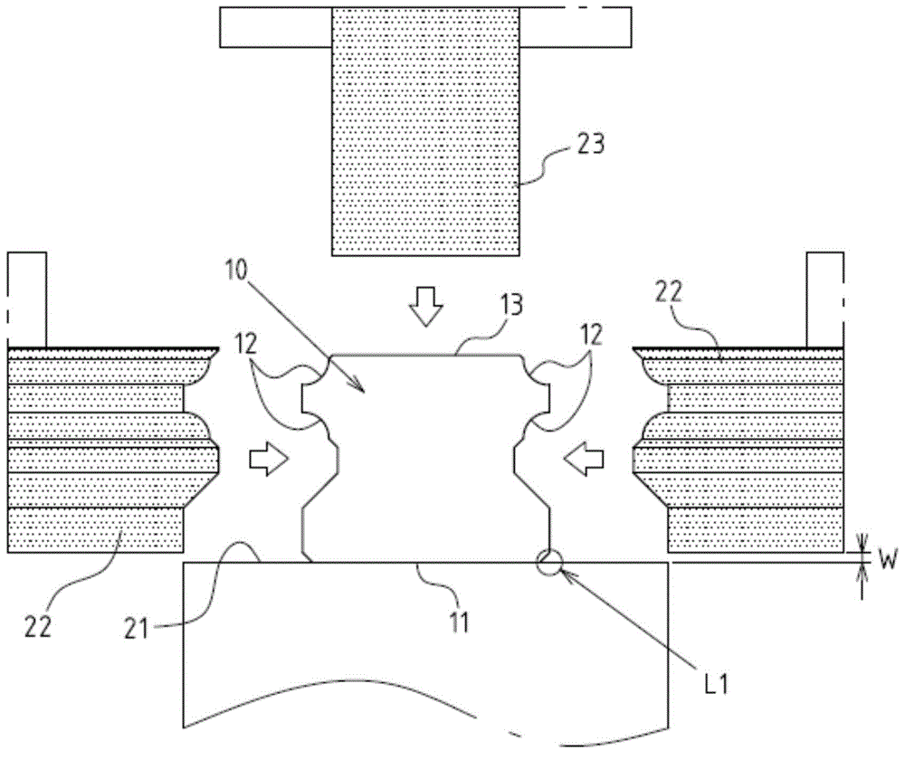
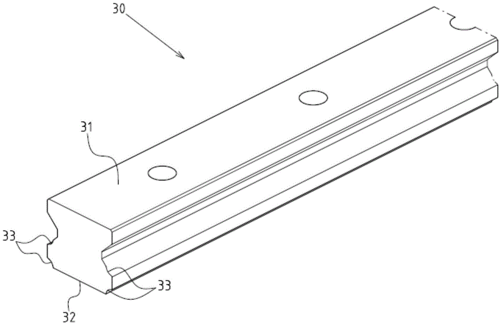
[0027] see Figures 2 to 7 As shown, it is a preferred embodiment of the linear slide rail grinding method and its grinding mechanism of the present invention; the linear slide rail 30 is detailed as image 3 As shown, it includes an assembly abutting surface 31, an end surface 32, and a pair of roller guide surfaces 33 formed on opposite sides of the linear slide rail 30 (note: the number of the roller guide surfaces 33 on each side without limitation); the method is carried out by a grinding mechanism 40, the grinding mechanism 40 includes: an elongated machine 405; a straddling stand part 41, which is arranged on the elongated machine in the form of a vertically spanning arch One place at 405; an actuating platform 42, which is set on the elongated machine platform 405 and can move forward and pass through the bottom of the cross-type stand part 41; a magnetic suction table 43, which is located on the actuating platform 42; Two vertical shaft type horizontal grinding wheel...


PUM


Abstract

The invention discloses a linear sliding rail grinding method and a grinding mechanism thereof. The grinding mechanism comprises a magnetic table arranged on an actuating platform, two vertical-shaft horizontal grinding wheels and a horizontal-shaft vertical grinding wheel, wherein the two vertical-shaft horizontal grinding wheels and the horizontal-shaft vertical grinding wheel are arranged on a saddle type stand unit. The top surface of the magnetic table is provided with a reducing magnetic convex surface which is in a convex state, and the reducing magnetic convex surface is smaller than the width of the end surface of a linear sliding rail; the linear rail is attached and positioned onto the reducing magnetic convex surface through the end surface of the linear sliding rail for performing precise finishing on the guide surface and the assembling attaching surface of a roller; the height of the bottom end surfaces of the two vertical-shaft horizontal grinding wheels is lower than that of the reducing magnetic convex surface but higher than that of the top surface of the magnetic table, so that the vertical-shaft horizontal grinding wheel can grind the corner parts connected between the end surface of the linear sliding rail and the guide surface of the roller. The linear sliding rail grinding method and the grinding mechanism thereof can achieve the aim of simplifying the grinding process of the linear sliding rail, reducing the processing errors and improving the processing quality.

Description

technical field [0001] The invention relates to a manufacturing and forming technology of a linear slide rail; in particular, it relates to a grinding method and a grinding mechanism including a linear slide rail. Background technique [0002] Linear slide rails are very important and indispensable guiding components for various precision processing equipment. The accuracy of linear slide rails is directly related to the operating accuracy and processing quality of precision processing equipment. Therefore, linear slide rails The precision requirements of the slide rail are quite strict in the manufacturing process, and almost every aspect of the slide rail needs to go through a precision grinding process to achieve the industry's preset precision requirements. [0003] In terms of its structural form, the linear slide rail mainly includes four surfaces, namely, an assembly abutment surface, an end surface, and two roller guide surfaces that are symmetrical to each other, an...

Claims


Application Information

Patent Timeline
Patent Type & Authority Applications(China)
IPC IPC(8): B24B37/00B24B37/27
CPCB24B19/004B24B27/0076B24B41/06
Inventor 林馨堂
Owner JOEN LIH MACHINERY
Why Eureka
Try Eureka