

Electrolytic copper foil, flexible circuit board and battery
A technology of electrolytic copper foil and battery, which is applied in the direction of circuits, battery electrodes, printed circuit components, etc. It can solve the problems of low profile of the precipitation surface, inability to have both flexibility and rigidity, and achieve improved anti-rust function and chemical resistance Quality, the effect of improving adhesion
Active Publication Date: 2015-03-18
FURUKAWA ELECTRIC CO LTD
View PDF8 Cites 5 Cited by
- Summary
- Abstract
- Description
- Claims
- Application Information
AI Technical Summary
Benefits of technology
This patented technology allows creating an electrically conductive material called electric current carrying metal (ECP) by applying specific treatment on its outer layers or inner surfaces beforehand. By doing this process, ECP becomes more effective against corrosions caused due to factors like moisture ingress and other environmental conditions such as temperature changes over time. Additionally, these treated materials have improved durability compared to untreatled ones while still maintain their effectiveness during use.
Problems solved by technology
The technical problem addressed in this patents relating to improving electrical performance and durability in printed circuits involves developing new methods for producing both highly pure and fine metal particles without causing defects on the final product due to contamination caused by residual solvents present within them.
Method used
View moreImage
Smart ImageViewing Examples

Examples
Embodiment 1~9、 comparative example 1~8
[0107] The manufacturing conditions such as electrolyte composition are shown in Table 1. The copper sulfate electroplating solution with the composition shown in Table 1 was cleaned through an activated carbon filter, and then the additives shown in Table 1 were added to prepare a specific concentration.
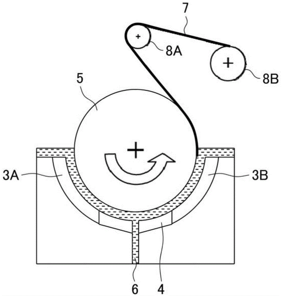
[0108] Will figure 2 The first anode 3 shown and the second anode 4 are adjusted to the current density and the anode length shown in table 2, using the same figure 2 The rotary drum foil-making device shown in the figure produces electrolytic copper foil with a thickness of 12 μm.
Login to View More PUM
| Property | Measurement | Unit |
|---|---|---|
| Thickness | aaaaa | aaaaa |
Abstract
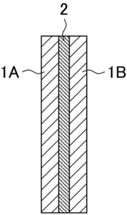
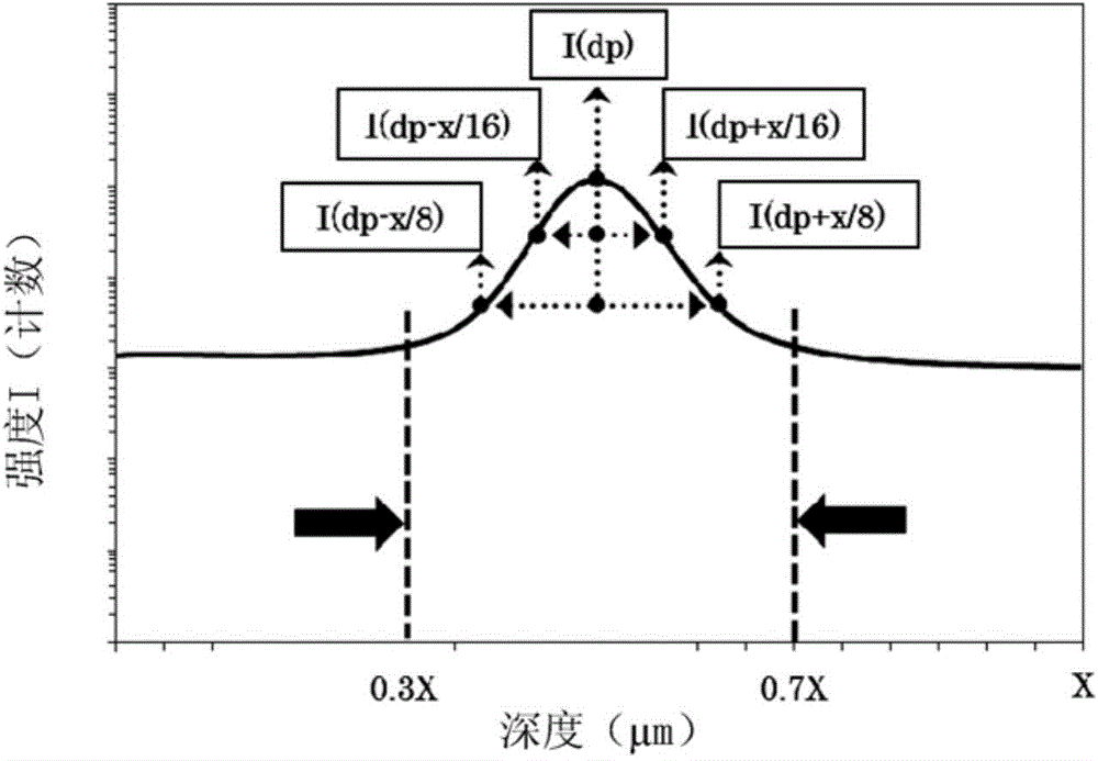
The invention provides an electrolytic copper foil which is suitable for circuit boards and batteries and has flexibility and rigidity. When Secondary ion mass spectroscopy (SIMS) on the depth direction on the S side or M side surface of the electrolytic copper foil with a thickness of X (mu m), the depth dp(mu m) that the peak values of the nitrogen (N), sulphur (S) or chlorine (Cl) nitrogen (N) appear in the sulphur (S) or chlorine (Cl) intensity profiles satisfies the 0.3x>=dp>=0.7x. Preferably, when the intensity (counting) is set as I(dp), the intensity of position x/8 away from the depth dp set as I(dp-x/8), I(dp+x/8) satisfies I(dp)>=100, I(dp-x/16)>=1.5* I(dp-x/8), I(dp+x/16)>=1.5* I(dp+x/8), I(dp)>=1.5* I(dp-x/8), and I(dp)>=1.5* I(dp+x/8).
Description
Login to View More Claims
Login to View More Application Information
Patent Timeline
 OwnerFURUKAWA ELECTRIC CO LTD