Engine oil-gas separation mechanism

A separation mechanism and engine technology, applied in the direction of engine components, machines/engines, engine lubrication, etc., can solve the problems of energy saving and environmental protection, inability to separate oil and gas, and high working temperature, and achieve simple structure, eliminate splashing, The effect of improving the environment

Inactive Publication Date: 2015-03-18
江苏普盛动力股份有限公司
View PDF11 Cites 2 Cited by
  • Summary
  • Abstract
  • Description
  • Claims
  • Application Information

AI Technical Summary

Problems solved by technology

[0002] The operating temperature of the single-cylinder diesel engine respirator in the prior art is relatively high, and it is directly connected with the external space. Oil and gas cannot be separated, causing environmental pollution, and the waste of machine oil is serious. function, but the effect is not good, so they cannot meet the requirements of energy saving and environmental protection

Method used


Image

  • Engine oil-gas separation mechanism

Examples


Embodiment Construction

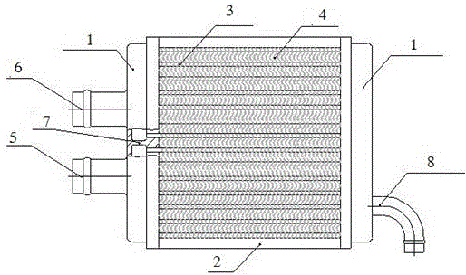
[0013] The present invention will be described in detail below in conjunction with the accompanying drawings.

[0014] An engine oil-gas separation mechanism, including a condenser, the two sides of the condenser are provided with clamping seats 1, and the other two sides are provided with splints 2 to fix the condenser together, one side of the condenser is provided with an outlet 5 and an inlet 6, and the condenser is composed of Condenser pipe 3 and heat sink 4 are composed, condenser pipe 3 is parallel to each other, arranged side by side between clamping seats 1, heat sink 4 is set on condenser pipe 3, outlet 5 and inlet 6 are separated by partition 7, condenser There is also a degreasing pipe 8 below, and a condensing pipe 3 is a 2*26 flat pipe made of 2A12 aluminum, which has high thermal conductivity and good heat dissipation effect. In addition, the oil removal pipe joint is arranged at the bottom, and the condensed oil can be drained in time to ensure that the breath...


PUM


Abstract

The invention discloses an engine oil-gas separation mechanism comprising a condenser. Two sides of the condenser are provided with clamping seats, and other two sides of the condenser are provided with clamping plats, in this way, the condenser is fixed. An oil removing pipe connector is arranged on the lower portion of the condenser, condensation oil can be discharged at any moment, a breath channel is kept smooth constantly, and a breather can run in long term. For mounting convenience on an air director, part of air generated by a flywheel fan is reasonably used, leading to good condensing effect. By the use of the engine oil-gas separation mechanism, air pressure in a crank case is stable, sputtering is avoided, engine oil temperature is lowered, the lubrication requirement is met, the engine oil can be recycled, energy sources are saved, environment improved, and low carbon and energy-saving effect is achieved.

Description

technical field [0001] The invention relates to the field of engine equipment, in particular to an engine oil-gas separation mechanism. Background technique [0002] The operating temperature of the single-cylinder diesel engine respirator in the prior art is relatively high, and it is directly connected with the external space. Oil and gas cannot be separated, causing environmental pollution, and the waste of machine oil is serious. function, but the effect is not good, so all can not meet the requirements of energy saving and environmental protection. Contents of the invention [0003] Purpose of the invention: In order to solve the deficiencies of the prior art, the present invention provides an engine oil-gas separation mechanism that can separate oil and gas, protect the surrounding environment, reduce engine oil temperature, ensure lubrication requirements, save engine oil, and meet energy-saving and environmental protection requirements. [0004] Technical solution...

Claims


Application Information

Patent Timeline
Patent Type & Authority Applications(China)
IPC IPC(8): F01M13/04F01M5/00
CPCF01M13/04F01M5/002F01M2013/0411
Inventor 洪里荣冯建立曹书余
Owner 江苏普盛动力股份有限公司
Why Eureka
Try Eureka