Hydraulic control system for reciprocating test beds

A technology of hydraulic control system and test bench, which is applied in the direction of fluid pressure actuation system components, fluid pressure actuation devices, accumulator devices, etc., can solve problems such as unsatisfactory operation status and complex structure, and achieve a high degree of automation , low operating cost, reasonable design effect

Inactive Publication Date: 2015-03-18
XIAN ZHIYUE ELECTROMECHANICAL TECH
View PDF0 Cites 10 Cited by
  • Summary
  • Abstract
  • Description
  • Claims
  • Application Information

AI Technical Summary

Problems solved by technology

Common reciprocating test benches are generally realized by crank-link mechanism, crank-slider mechanism, crank-rocker mechanism, eccentric wheel mechanism or cam spring mechanism. These mechanisms generally have problems such as complex structures and unsatisfactory operating conditions. Hydraulically driven The reciprocating test bench solves the above problems well

Method used


Image

  • Hydraulic control system for reciprocating test beds

Examples


Embodiment Construction

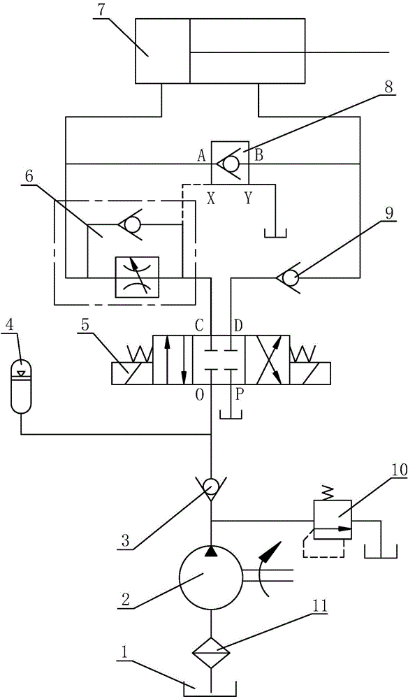
[0020] Such as figure 1 A hydraulic control system for a reciprocating test bench is shown, including an oil tank 1, a hydraulic pump 2 for supplying high-pressure hydraulic oil to the system, and a hydraulic cylinder 7 for driving the reciprocating motion of the component under test, as well as a reversing valve 5, a one-way speed regulation Valve 6 and hydraulic control check valve 8; port C and port D of the reversing valve 5 communicate with the rodless chamber and the rod chamber of the hydraulic cylinder 7 respectively, and port P of the reversing valve 5 communicates with the port O The ports are respectively communicated with the oil outlet of the oil tank 1 and the hydraulic pump 2, the oil outlet of the hydraulic pump 2 is provided with an accumulator 4, and the accumulator 4 can play a role when the hydraulic pump 2 is not working. The role of energy storage and pressure maintenance. The one-way speed regulating valve 6 is arranged on the pipeline between the port ...


PUM


Abstract

The invention discloses a hydraulic control system for reciprocating test beds. The hydraulic control system comprises a reversing valve, a one-way speed control valve and a hydraulic control one-way valve. A first working port and a second working port of the reversing valve are respectively communicated with a rodless cavity and a rod cavity of a hydraulic cylinder, a third working port and a fourth working port of the reversing valve are respectively communicated with oil outlets of an oil tank and a hydraulic pump, an accumulator is mounted on the oil outlet of the hydraulic pump, the one-way speed control valve is mounted on a pipe arranged between the first working port of the reversing valve and the rodless cavity of the hydraulic cylinder, the rodless cavity and the rod cavity of the hydraulic cylinder are respectively communicated with an oil inlet and an oil outlet of the hydraulic control one-way valve, a hydraulic control oil port of the hydraulic control one-way valve is respectively communicated with the first working port of the reversing valve and the oil tank. The hydraulic control system for reciprocating test beds has the advantages of reasonable design, good using effects, high automation level, low cost, mechanic-electric-hydraulic integrative design, high intelligent level, stable and reliable operation and long service life.

Description

technical field [0001] The invention belongs to the technical field of hydraulic transmission and relates to a hydraulic control system, in particular to a hydraulic control system for a reciprocating test bench. Background technique [0002] The reciprocating test refers to the reciprocating movement of the tested part under the action of external force. The function of the reciprocating test bench is to simulate the working conditions of a certain component, and conduct a compression test at a frequency of 5-50 times / min to assess the reliability of the internal seal of the tested component. Common reciprocating test benches are generally realized by crank connecting rod mechanism, crank slider mechanism, crank rocker mechanism, eccentric wheel mechanism or cam spring mechanism. These mechanisms generally have problems such as complex structure and unsatisfactory operating status. The reciprocating test bench solves the above problems well. Contents of the invention ...

Claims


Application Information

Patent Timeline
Patent Type & Authority Applications(China)
IPC IPC(8): F15B1/02F15B11/08F15B13/02F15B21/04
CPCF15B1/024F15B11/08F15B13/02F15B21/041
Inventor 黄冰
Owner XIAN ZHIYUE ELECTROMECHANICAL TECH
Why Eureka
Try Eureka