Controllable dynamic sliding scanning excitation method for seismic sources

A sliding scanning and dynamic technology, applied in the field of geophysical exploration, can solve problems such as large excitation efficiency, and achieve the effect of improving blasting efficiency

Active Publication Date: 2015-03-18
BC P INC CHINA NAT PETROLEUM CORP +1
View PDF7 Cites 8 Cited by
  • Summary
  • Abstract
  • Description
  • Claims
  • Application Information

AI Technical Summary

Problems solved by technology

[0009] The disadvantage of the simultaneous scanning of the vibrator currently used is that the simultaneous scanning excitation can only be completed when the distance between the two shots is greater than the minimum simultaneous scanning distance and they are ready at the same time. When the distance is less than the minimum simultaneous scanning distance and the time interval > 0 In the case of sliding scan excitation, only the sliding scan excitation method can be used, and between the sliding scan excitation and the simultaneous scanning excitation, that is, the distance is less than the minimum simultaneous excitation distance and the time is less than the sliding scan time, there are many conditions that are not included.
[0010] There is no distance limit between the sliding scanning and alternating scanning excitation methods currently used, but according to the degree of source interference, in the case of a large distance between the two sources, a smaller time interval can be used, and when the distance is small to a certain amount Afterwards, only alternate scanning with the least interference can be used, and the maximum excitation efficiency cannot be guaranteed with the minimum interference.

Method used


Image

  • Controllable dynamic sliding scanning excitation method for seismic sources
  • Controllable dynamic sliding scanning excitation method for seismic sources
  • Controllable dynamic sliding scanning excitation method for seismic sources

Examples


Embodiment Construction

[0030] The present invention will be described in detail below in conjunction with accompanying drawings and examples.

[0031] The present invention adopts following steps to realize:

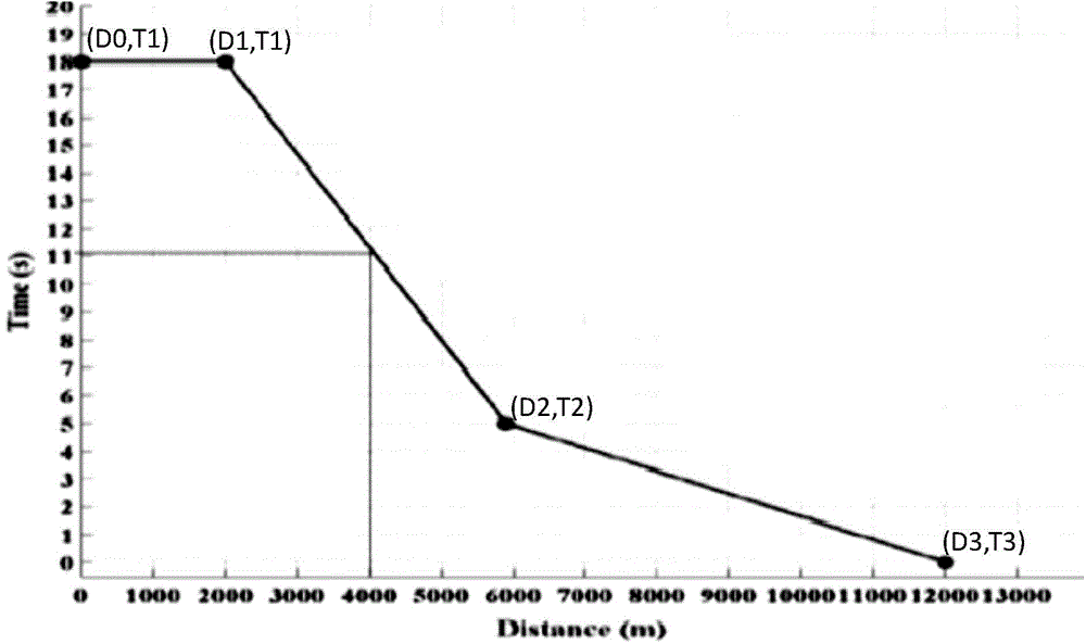
[0032] 1) Establish a coordinate system with the distance D between the seismic sources as the horizontal axis and the time interval T between the front and rear shots as the vertical axis, connecting the alternate scanning points (D0, T1), (D1, T1), and the sliding scanning points (D2, T2) and simultaneous scanning points (D3, T3) form a dynamic sliding scanning curve, such as figure 1 shown;

[0033] Said D0 and D1 are the minimum distance range set by alternate scanning, D1>D0, and T1 is the minimum time interval of alternate scanning;

[0034] The D2 is the maximum distance set by the sliding scan, and the minimum time interval of the T2 sliding scan;

[0035] The D3 is the minimum distance set for simultaneous scanning, and T3 is the time interval of simultaneous scanning, which is 0 v...


PUM


Abstract

The invention discloses a controllable dynamic sliding scanning excitation method for seismic sources in the process of acquiring seismic data. A coordinate system of taking the distance D between every two seismic sources as an abscissa axis and taking a time interval T between a front cannon and a rear cannon as a longitudinal axis is established; alternative scanning points, sliding scanning points and simultaneous scanning points are connected to form a dynamic sliding scanning curve; the adjustment of the excitation is realized according to the values of the distance D between every two seismic sources and the time interval T between the front cannon and the rear cannon. According to the method disclosed by the invention, by the method of adopting different excitation modes under the conditions of setting different distances of the seismic sources and the time intervals, the proportion that the seismic sources simultaneously vibrate can be improved, the time interval of blasting time of the two cannons is compacted on the whole, and further the blasting efficiency is greatly improved.

Description

technical field [0001] The invention belongs to the technical field of geophysical exploration, and relates to a vibrator dynamic sliding scanning excitation method in seismic data acquisition. Background technique [0002] When using a vibrator for seismic acquisition, it takes a few seconds to tens of seconds for the vibrator to complete a vibration. A vibration is also a scan, and the time used is called the scan time. According to construction requirements, the excitation of a shot point can be done by The vibration of a single source can be completed at one time, and it can also be completed by combining the vibration of several sources. No matter what parameters are used, it takes a certain amount of time to complete the excitation of a shot point. In order to improve the vibration efficiency and adapt to high-precision, high-density earthquakes With the development of exploration, various high-efficiency excitation methods of vibrators have been proposed and applied, ...

Claims


Application Information

Patent Timeline
Patent Type & Authority Applications(China)
IPC IPC(8): G01V1/104
Inventor 梁晓峰汪长辉邓志文鄂殿梁侯成福
Owner BC P INC CHINA NAT PETROLEUM CORP
Why Eureka
Try Eureka