
Intelligent dehumidification system of electrical equipment

A kind of power equipment and intelligent technology, applied in the direction of control/regulation system, non-electric variable control, instrument, etc., can solve problems such as hidden dangers in the safe operation of live equipment, phase-to-phase short-circuit faults, etc.

Inactive Publication Date: 2015-03-18
STATE GRID CORP OF CHINA +1
View PDF9 Cites 10 Cited by
  • Summary
  • Abstract
  • Description
  • Claims
  • Application Information

AI Technical Summary

Problems solved by technology

The accumulation of moisture in the bus barrel brings great hidden dangers to the safe operation of live equipment, and can easily lead to phase-to-phase short-circuit faults

Method used


Image

  • Intelligent dehumidification system of electrical equipment
  • Intelligent dehumidification system of electrical equipment
  • Intelligent dehumidification system of electrical equipment

Examples


Embodiment Construction

[0020] Below in conjunction with accompanying drawing and specific embodiment the present invention will be described in further detail:

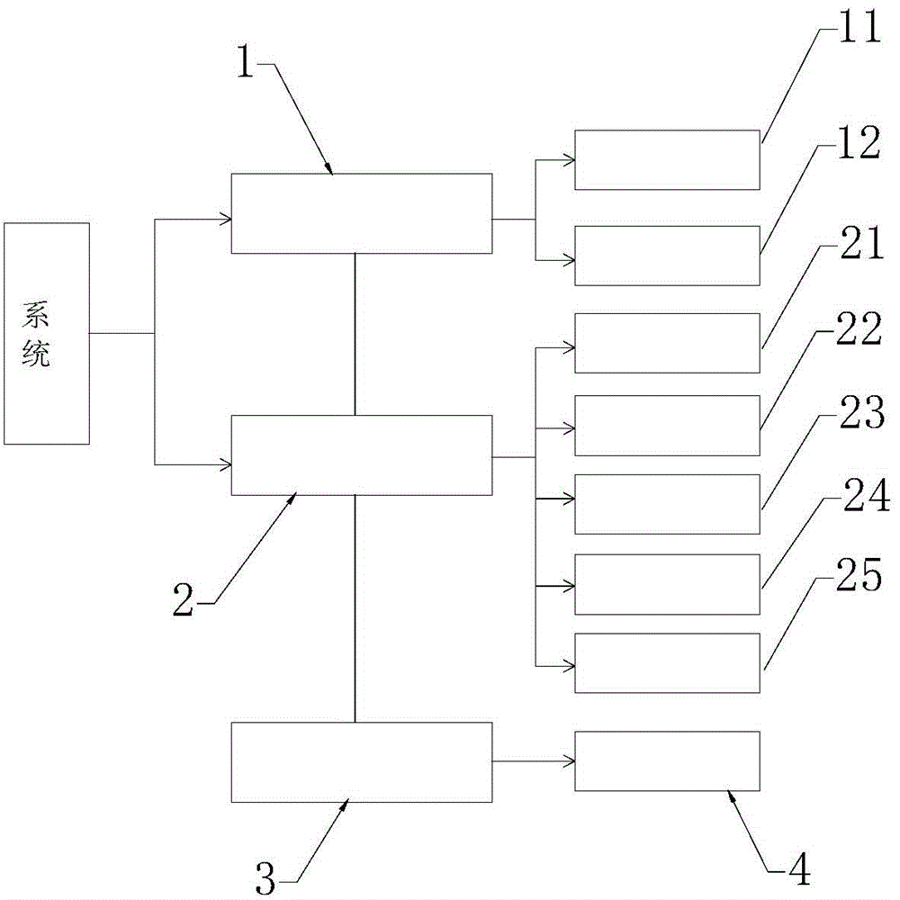
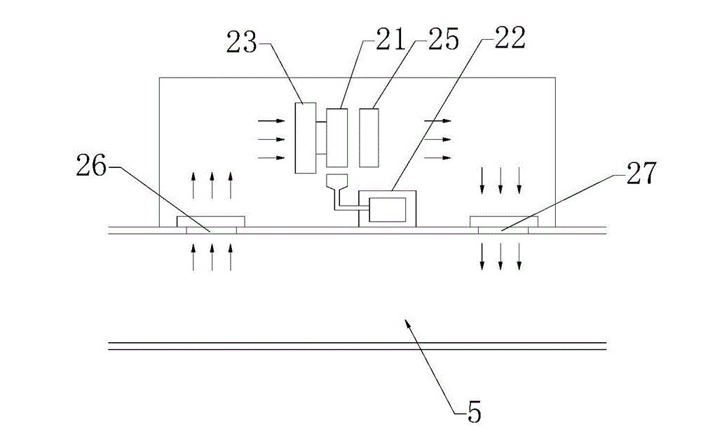
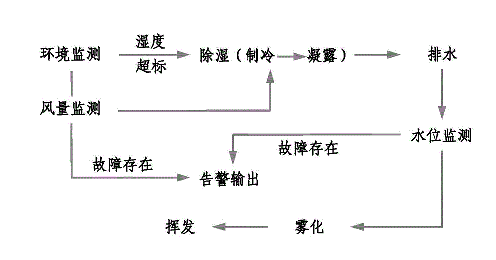
[0021] see Figure 1 to Figure 3 , the present invention includes an intelligent control unit 1 and an environment control unit 2, the intelligent control unit 1 and the environment control unit 2 are both provided with terminals and connected to each other.

[0022] The intelligent control unit 1 includes

[0023] a main control unit 11, configured to control the environment control unit 2 to work, and

[0024] A system power supply unit 12, configured to provide power supply for the system,

[0025] The environmental control unit 2 includes

[0026] The dehumidification unit 21 is used to condense and separate the moisture in the air in the power equipment 5. On the basis of applying insulating paint to the conductors, in order to completely eliminate the phenomenon of moisture accumulation in the busbar barrel of the power equipment 5...


PUM


Abstract

The invention discloses an intelligent dehumidification system of electrical equipment. The intelligent dehumidification system comprises an intelligent control unit and an environment control unit, wherein the intelligent control unit comprises a master control unit and a system power supply unit; the environment control unit comprises a dehumidification unit, an atomization unit, a forced circulation unit and a monitoring unit. According to the system, the environment can be simultaneously monitored, LED (Light Emitting Diode) digital display can be realized, and the temperature and the humidity can also be correspondingly set and displayed respectively. The intelligent control unit can be used for automatically controlling the environment control unit according to site conditions. Moisture discharged by the equipment is forcibly evaporated by using the atomization unit and is safely discharged. The system is a piece of preferred environment monitoring equipment for guaranteeing high-efficiency and safe operation of an intelligent power grid.

Description

technical field [0001] The invention relates to the fields of electrical equipment and electrical engineering, in particular to an intelligent dehumidification system for electrical equipment. Background technique [0002] At present, in the typical design of substations of various voltage levels, more indoor substation designs are adopted. In order to meet the requirements of equipment operation reliability and safety, the lead wires of the power supply inlet and outlet intervals and the main transformer interval are basically electrically connected in the form of closed busbar barrels. With the increase of the operating life and the aging of some components, the operating defects or hidden dangers are becoming more and more prominent. After long-term monitoring and operation data summary analysis of the substation equipment, the main reason is that the equipment has been in a humid operating environment for a long time and cannot be effectively treated and The air insulati...

Claims


Application Information

Patent Timeline
IPC IPC(8): G05D27/02
Inventor 杜勇高建伟曹北建王靖宇张校东郑军宋长勇高峰焦岩李岩窦永东陈晓旭
Owner STATE GRID CORP OF CHINA
Learn More