Inductor and manufacturing method thereof

A technology of inductors and manufacturing methods, applied in the field of inductors and their manufacturing methods, can solve problems such as increased manufacturing time, poor electrical properties, and waste generation, and achieve the effects of reducing manufacturing costs and increasing production efficiency

Inactive Publication Date: 2015-03-18
重庆美桀电子科技有限公司
View PDF6 Cites 5 Cited by
  • Summary
  • Abstract
  • Description
  • Claims
  • Application Information

AI Technical Summary

Problems solved by technology

[0004] However, figure 1 The inductor shown has many disadvantages in the manufacturing process, for example: the I-shaped core 11 is directly processed, and waste will be generated during the cutting process; secondly, the core 11 and the base 10 need to be bonded first The coil injection process can be carried out, and then the wiring part 122 is fixed on the base 10, which increases the production time; in addition, the combination of the shell 13, the core body 11 and the base 10 requires alignment technology, otherwise it is easy to cause electric shock. Dyssexuality

Method used


Image

  • Inductor and manufacturing method thereof
  • Inductor and manufacturing method thereof
  • Inductor and manufacturing method thereof

Examples


Embodiment Construction

[0021] The implementation of the present invention is described below through specific examples, and those skilled in the art can easily understand other characteristics and functions of the present invention from the content disclosed in this specification. The present invention can also be implemented or applied through other different specific embodiments.

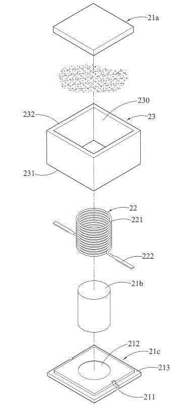
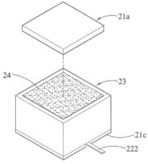
[0022] refer to Figure 2A , 2B , 2C and Figure 2D , illustrating the basic components of the inductor of the present invention.

[0023] exist Figure 2A Among them, the magnetic core post 21b is arranged on the first magnetic end cap 21c, the second magnetic end cap 21a is arranged on the magnetic core post 21b, and the first magnetic end cap 21c and the second magnetic end cap 21a abut against the magnetic core post 21b At both ends, the three form an I-shape.

[0024] Generally speaking, the materials of the magnetic core post 21b and the first and second magnetic end caps 21c and 21a can be, for example, cera...


PUM


Abstract

The invention discloses an inductor and a manufacturing method thereof. The manufacturing method includes that one end of a magnetic core column is abutted against a first magnetic end cap, a coil with two connecting parts is sleeved with the magnetic core column, the two connecting parts are arranged in two opening holes, and then the first magnetic end cap covers the first end of a shell with an accommodation space, so that the magnetic core column and the coil can be accommodated in the accommodation space; magnetic powder is filled into the accommodation space to form a magnetic powder layer so as to cover the coil and the magnetic core column, and then a second magnetic end cap covers the second end of the shell and is abutted against the other end of the magnetic core column, so that the magnetic powder layer and the coil sleeved with the magnetic core column are sealed in the accommodation space, and the two connecting part are bent towards one side of the first magnetic end cap away from the shell. The magnetic core column and the first and second magnetic end caps can be manufactured by different materials, magnetic saturation characteristics of the inductor can be added, and manufacturing cost is reduced.

Description

technical field [0001] The present invention relates to an inductor and a manufacturing method thereof, in particular, to an inductor capable of reducing manufacturing costs and a manufacturing method thereof. Background technique [0002] Inductor is a kind of passive component, which has the functions of filtering and removing noise, suppressing instantaneous current, reducing EMI (Electromagnetic Interference, electromagnetic interference) and power conversion. It has been widely used in various electronic products for a long time. [0003] figure 1 It is a schematic diagram of an existing inductor. Firstly, an I-shaped core 11 is glued on the base 10, and then a wire is helically wound around the core 11 by a coil injection device to form a coil 12, and the helical part 121 is formed around On the core 11 , the wiring part 122 extends from both ends of the helical part 121 and is fixed on the base 10 . Finally, the shell 13 is assembled so that the core 11 and the coil ...

Claims


Application Information

Patent Timeline
Patent Type & Authority Applications(China)
IPC IPC(8): H01F17/04H01F27/28H01F27/26H01F41/00
Inventor 罗鹏程
Owner 重庆美桀电子科技有限公司
Why Eureka
Try Eureka