Inertial power generation device with power generating unit and acceleration direction detection device
A technology for a power generation device and a power generation unit, which is applied to electromechanical devices, generators/motors, electrical components, etc., can solve the problems of application constraints, the acceleration direction detection device relies on an external power supply, etc., and achieves wide application, simple structure, and low cost. Effect
- Summary
- Abstract
- Description
- Claims
- Application Information
AI Technical Summary
Problems solved by technology
Method used
Image
Examples
no. 1 example
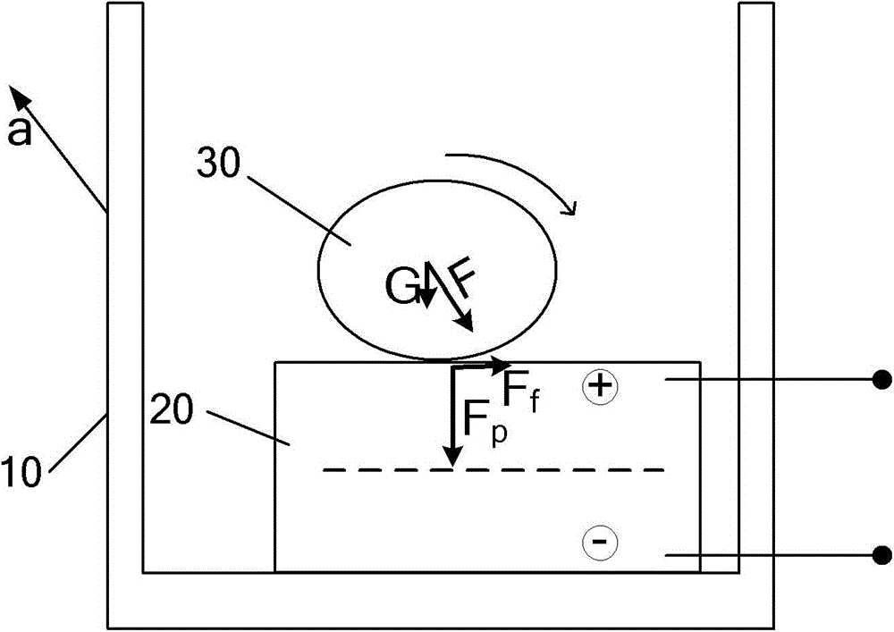
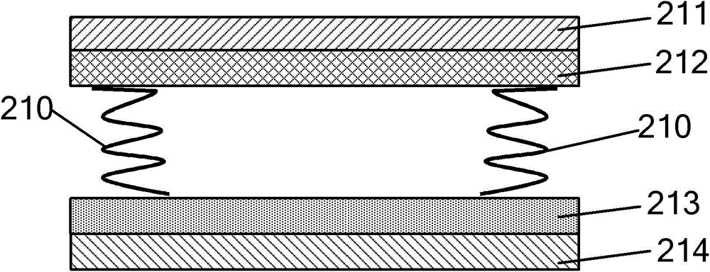
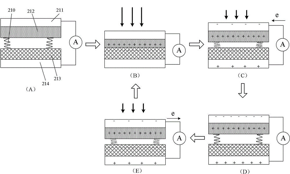
[0073] The first embodiment is a cylindrical inertial power generator. Image 6 A cross-sectional view of the cylindrical power plant is shown. see Image 6 , the inertial power generation device includes a cylindrical housing 11 (base), a plurality of power generators uniformly arranged on the inner surface of the housing 11 (that is, the top surface and the bottom surface that are not perpendicular to the central axis of the cylinder) The unit 21 and a cylindrical roller 31 , wherein the roller 31 is placed in a cavity in the housing 11 . When the housing 11 is subjected to an external force, the rollers 31 move in the housing 11 due to inertial force. The power generating unit 21 outputs an electric signal under the action of the roller 31 .
[0074] In this embodiment, the gaps between the plurality of power generating units 21 are smaller than the diameter of the cylindrical rollers 31 , so that the rollers 31 will not get stuck between the power generating units, but ...
no. 2 example
[0079] The second embodiment is a modified embodiment of the first embodiment. Figure 8 A block diagram of this second embodiment is shown. like Figure 8 As shown, the difference from the first embodiment is that the power generating unit 21 is placed inside the casing 11, and the moving body in the casing 11 is a rolling body 31 that cannot roll, but a flat body that can only move in translation. The moving body 32, and there are elastic connecting members 41 between the translational body 32 and the housing 11, in an example, there are four, such as Figure 8 shown.
[0080] In this embodiment, the housing 11 may be in any shape, not limited to a cylindrical shape. When the casing 11 is subjected to an external force, the translational body 32 reciprocates in the casing 11 (in the direction of arrow B), and respectively exerts force on the power generating units 21 inside the casing to generate electric energy.
no. 3 example
[0082] The third embodiment is an acceleration direction detecting device. The acceleration direction detection device is a further improvement on the basis of the inertial power generation device of the present invention. As mentioned above, the power generation unit in the inertial power generation device can convert the mechanical energy generated by the inertial force acting on the moving body into an electrical signal. The electrical signal accurately reflects the direction of motion of the moving body, and, through further design of the moving body, the direction of motion accurately reflects the direction of the inertial force it receives. In this way, by measuring the electrical signals generated by each power generation unit, the direction of the inertial force on the moving body can be measured. According to the inertial force received by the moving body and the acceleration direction of the base body, the acceleration of the base body is obtained.
[0083] As prev...
PUM
 Abstract
Description
Claims
Application Information
 - R&D
- Intellectual Property
- Life Sciences
- Materials
- Tech Scout
- Unparalleled Data Quality
- Higher Quality Content
- 60% Fewer Hallucinations
Browse by: Latest US Patents, China's latest patents, Technical Efficacy Thesaurus, Application Domain, Technology Topic, Popular Technical Reports.
© 2025 PatSnap. All rights reserved.Legal|Privacy policy|Modern Slavery Act Transparency Statement|Sitemap|About US| Contact US: help@patsnap.com


