
Rock crusher

A pulverizer and rock technology, which is applied in grain processing and other directions, can solve the problems of inability to crush rocks, influence on accuracy and reliability, and low precision of test piece preparation, so as to ensure the operation of equipment and ensure the reliability.

Inactive Publication Date: 2015-03-25
CHINA THREE GORGES UNIV
View PDF0 Cites 2 Cited by
  • Summary
  • Abstract
  • Description
  • Claims
  • Application Information

AI Technical Summary

Problems solved by technology

[0002] At present, the methods for measuring rock density include volumetric method and wax sealing method, but these two methods have the following problems: the preparation accuracy of the test piece is not high, which leads to low results of the volumetric method; and reliability are affected; soft rocks that disintegrate and dissolve in water cannot be weighed in water
In view of these problems, the use of rock crushers to measure the density of rocks can solve the above drawbacks. The method is simple, fast, stable, practical, and has a wide range of measurement. The test results are consistent with the standard method, which shows that it has certain accuracy and reliability. It meets the requirements of relevant regulations, and can also achieve the purpose of rock porosity and speed up the reaction rate of rock and solution, but the rock needs to be deeply crushed. The current ordinary rock crushers are industrially used crushers, which cannot crush the rock Crushed to the fineness suitable for determining the density of rocks, and the volume is large and inconvenient to operate

Method used


Image

  • Rock crusher
  • Rock crusher

Examples


Embodiment Construction

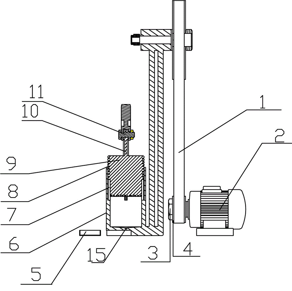
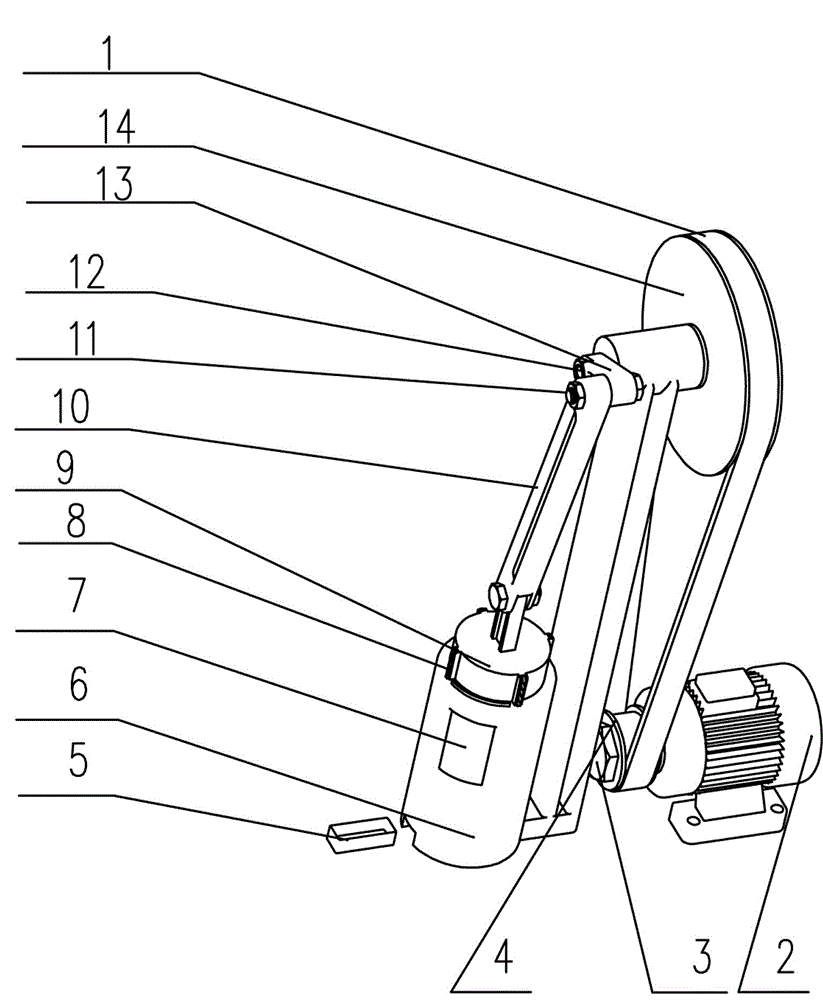
[0012] The structure of the present invention is as figure 1 -2 shows: a rock crusher, including a servo motor 2, the output shaft of the servo motor 2 is a small pulley shaft 3, the small pulley 4 is matched with the small pulley shaft 3, the large pulley 14 and the small pulley 4 There is a belt 1 in between, the large pulley 14 is connected to the large pulley shaft 12, the large pulley shaft 12 is connected to the I-shaped connecting rod 10 through the I-shaped crank 13, and the I-shaped crank 13 and the I-shaped connecting rod 10 are connected to the shaft through the crank connecting rod. 11 is connected, the I-shaped connecting rod 10 is connected with the drum block 9 in the main machine 6 of the crusher, the drum bar 8 is installed around the drum block 9 and the drum bar 8 matches the pulley groove on the main machine 6, and the main machine 6 A circular small hole 15 is opened in the center of the inner bottom, and the small hole 15 penetrates to the bottom groove, an...


PUM


Abstract

The invention discloses a rock crusher which comprises a servo motor, a small belt pulley shaft and a large belt pulley, wherein a belt is arranged between the large belt pulley and a small belt pulley; the large belt pulley is connected with a large belt pulley shaft; the large belt pulley shaft is connected with an I-shaped connecting rod by virtue of an I-shaped crank; the I-shaped crank is connected with the I-shaped connecting rod by virtue of a crank connecting rod connecting shaft; the I-shaped connecting rod is connected with a tamper slide block in a main engine of the crusher; roller strips are arranged at the periphery of the tamper slide block and are matched with pulley grooves in the main engine; a circular small hole which penetrates through a bottom groove is formed in the center of the bottom in the main engine; and a receiving container is arranged at the lower part of the main engine. The rock powder crushed by the rock crusher disclosed by the invention can reach a millimeter scale, and the reliability of the result is guaranteed; a movable plate on an observation window is made of transparent toughened glass, so that the operating state of the main engine is conveniently observed and the rock scraps are cleaned; and moreover, the cylindrical inner wall of the main engine and the cylindrical outer wall of the tamper are coated with porcelain glaze, the smoothness is very high, dust is extremely difficultly adhered to the crusher, and smooth equipment operation is guaranteed.

Description

Technical field [0001] The invention relates to a crushing device, in particular to a rock crusher. Background technique [0002] The current methods for measuring rock density are volumetric method and wax-sealing method, but these two methods have the following problems: the preparation accuracy of specimens is not high, which leads to low volumetric method results; the wax-sealing method has cumbersome procedures, difficult to grasp, and accuracy. And reliability is affected; soft rock that disintegrates and dissolves in water cannot be weighed in water. In response to these problems, the use of a rock crusher to determine the density of rocks can solve the above drawbacks. The method is simple, fast, stable, practical, and has a wide measurement range. The test results are consistent with the standard method, which shows that it has a certain accuracy and reliability. To meet the requirements of relevant regulations, it can also achieve the purpose of rock porosity and speed...

Claims


Application Information

Patent Timeline
Patent Type & Authority Applications(China)
IPC IPC(8): B02C1/00
Inventor 刘杰金晶李建林
Owner CHINA THREE GORGES UNIV
Learn More