Crushing press used in kitchen

A technology for presses and kitchens, used in presses, grain processing, manufacturing tools, etc., can solve the problems that materials cannot be pressed and dehydrated, cannot be squeezed and crushed, and filter failures, etc., and achieve high crushing and pressing efficiency. Novel, quick installation effect

Active Publication Date: 2015-03-25
SHANDONG SHUANGLUN
View PDF7 Cites 12 Cited by
  • Summary
  • Abstract
  • Description
  • Claims
  • Application Information

AI Technical Summary

Problems solved by technology

No matter whether the food waste is first dehydrated by a press and then pulverized by a pulverizer, or pulverized by a pulverizer first and then dehydrated by a press, food waste cannot be processed efficiently
[0004] In order to solve the above technical problems, CN102357515B discloses a crushing and pressing machine for food waste, which includes a crushing part and a pressing and dehydrating part. Moving shaft; gears are installed on the driving shaft and driven shaft, and the gears include a gear ring and a washer, and the gear ring is provided with gear teeth; its disadvantages: one is that plastic bottles, rags are included in the leftovers of the meal Such as some large materials, during the mutual movement of the driving shaft and the driven shaft, it is easy to wind up on the gears of the driving shaft and the driven shaft, resulting in the inability to crush; the second is that the threaded blades in the dehydration part of the press only serve as a guide. In addition, the waste water squeezed out during the pressing process flows out through the filter screen. Since the meal waste is relatively viscous during the pressing process, it is easy to seal the filter screen, resulting in filtration Ineffective, so that the crushed material cannot achieve the function of pressing and dehydrating

Method used


Image

  • Crushing press used in kitchen
  • Crushing press used in kitchen

Examples


Embodiment Construction

[0017] The present invention is further described below in conjunction with accompanying drawing:

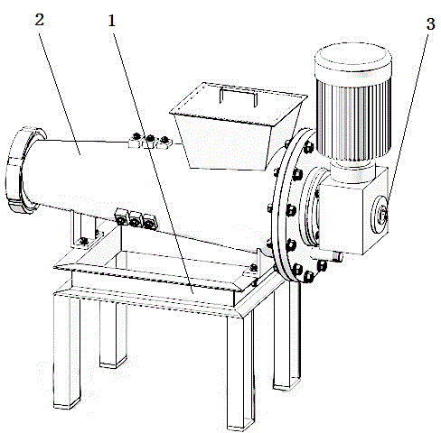
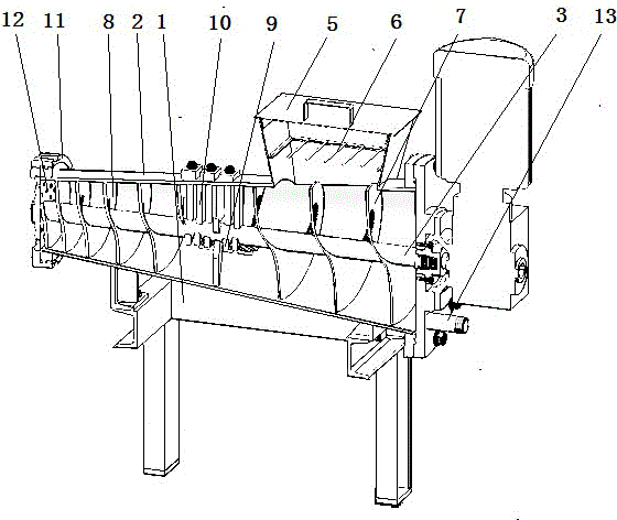
[0018] As shown in the accompanying drawings, a kitchen crushing press includes a frame 1, a cylinder body 2, a transmission shaft 3 and a power source, the cylinder body 2 is fixed on the upper end of the frame 1, and the cylinder body 1 is provided with Transmission shaft 3, the transmission shaft 3 is provided with a helical blade knife, and the transmission shaft 3 is driven by a power source, and it is characterized in that an intercepting grid 6 is horizontally provided on the feeding hopper 5 at the upper end of the cylinder body 2, so as to facilitate Isolate the larger bottles, cans, rags or napkins in the food waste, and let the soft food waste materials enter the cylinder, driven by the transmission shaft, so that the materials are crushed and squeezed out under the action of the spiral blade knife.

[0019] The barrel 2 of the present invention is conical, and the di...


PUM


Abstract

The invention discloses a crushing press used in a kitchen. The crushing press comprises a rack, a barrel, a transmission shaft and a power source, wherein a screw blade knife is arranged on the transmission shaft. The crushing press is characterized in that an intercepting grid is horizontally arranged on a feeding hopper at the upper end of the barrel; the barrel is in a conical shape; the diameter of the barrel is gradually reduced from the feeding end to the discharge end; a liquid outlet is formed in the bottom of the large-diameter end of the barrel, liquid of pressed and crushed materials flows to the liquid outlet through the gradient of the barrel, and is discharged through the liquid outlet, and thus the target of automatically discharging liquid is achieved; the screw blade knife on the transmission shaft is a screw blade with a conical gradual changing pitch; and the outer diameter conicity of the screw blade is the same as that of a taper clearance in the inner wall of the barrel, so that leftovers are crushed and pressed out under the variable pitch action of the screw blade knife. The crushing press has the advantages of being novel in structure, convenient to use, free of blockage, high in crushing and pressing efficiency, reliable in performance, fast to install and the like.

Description

technical field [0001] The invention relates to the technical field of kitchen processing equipment, in particular to a kitchen crushing press. Background technique [0002] As we all know, with the continuous development of the economy, people's living standards are getting higher and higher, and there are more and more domestic waste, among which kitchen waste (also called kitchen waste) occupies a large proportion of garbage. The main characteristics of kitchen waste are rich in organic matter, high in water content, and perishable. Its properties and odor will have a bad impact on environmental sanitation, and it is easy to breed harmful substances such as pathogenic microorganisms and mycotoxins. If it is not handled properly, it will bring people Extremely serious danger. On the other hand, nutrient-rich food waste is also a valuable renewable resource. Food waste that has been properly treated can be reused. [0003] At present, people often use a press to dehydra...

Claims


Application Information

Patent Timeline
Patent Type & Authority Applications(China)
IPC IPC(8): B02C18/00B30B9/14B09B3/00
CPCB02C18/14B02C18/18B09B3/00B30B9/14
Inventor 刘元成
Owner SHANDONG SHUANGLUN
Why Eureka
Try Eureka