Welding jig for motor stator core and welding method thereof

A welding fixture and motor stator technology, applied in welding equipment, welding equipment, auxiliary welding equipment and other directions, can solve the problems of high production cost, low production efficiency, unqualified appearance, etc., to reduce investment, eliminate welding slag, and avoid artificial The effect of the influence of uncertainty

Active Publication Date: 2017-01-04
NANTONG TONGDA SILICON STEEL STAMPING TECH CO LTD
View PDF7 Cites 0 Cited by
  • Summary
  • Abstract
  • Description
  • Claims
  • Application Information

AI Technical Summary

Problems solved by technology

[0003] The above problem to be solved by the present invention is to provide a motor stator core that can improve production quality and production efficiency in view of the low production efficiency, unqualified appearance, unstable quality, and high production cost of the above-mentioned prior art. welding fixture

Method used


Image

  • Welding jig for motor stator core and welding method thereof

Examples


Embodiment Construction

[0026] The present invention is described in further detail now in conjunction with accompanying drawing. These drawings are all simplified schematic diagrams, which only illustrate the basic structure of the present invention in a schematic manner, so they only show the configurations related to the present invention.

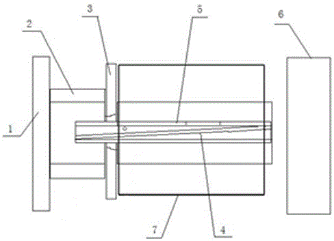
[0027] Such as figure 1 Shown, a kind of welding method of the welding jig of motor stator iron core comprises the following steps:

[0028] (1) Assemble all the parts, the welding jig of the motor stator core, including the support plate 1, the bushing 2, the tailgate 3, the oblique key 4 and the oblique key substrate 5; the support plate 1 is arranged vertically, and the The bush 2 is horizontally fixed on one side of the support plate 1, and the bush 2 is provided with a shoulder for positioning the tailgate 3, and the tailgate 3 is sleeved on the bush 2 and limited Located at the shoulder of the bushing 2, the bushing 2 is also fixed with a slant key sub...


PUM


Abstract

The invention discloses a welding jig for a motor stator core and a welding method thereof. Horizontally fixed on one side of the support plate, the bush is provided with a shoulder for positioning the rear baffle, the rear baffle is sleeved on the bush and limited to the shoulder of the bush, the The bushing is also fixed with a slanted key substrate, the slanted key substrate is fixed with a slanted key for positioning the stator core, and the front pressure plate for applying extrusion thrust to the motor punch is installed on the bushing on the free end. Compared with the prior art, the invention has the beneficial effects of: reducing the labor intensity of workers, improving work efficiency; ensuring the quality of welding, reducing labor cost input, and being suitable for the production of motor iron cores of different lengths, reducing Equipment investment, saving production costs.

Description

technical field [0001] The invention belongs to the field of motor and generator manufacturing, is suitable for welding iron cores of different lengths, and in particular relates to a welding jig for a motor stator iron core and a welding method thereof. Background technique [0002] In the prior art, after the press-fitting process of the stator core, the welding is generally carried out by turning the shaft on the ground manually. This method is labor-intensive and the workers are prone to fatigue, resulting in low work efficiency and increased production costs. In the process of operation, the outer circle is also easy to cause bumps, which affects the appearance quality and cannot meet the requirements of high-end customers for the motor core. In addition, during welding, due to the influence of human factors, there are unstable factors in manual welding, such as: the welding speed is not stable, the surface welding is uneven, there are human errors, etc., resulting in r...

Claims


Application Information

Patent Timeline
Patent Type & Authority Patents(China)
IPC IPC(8): B23K37/04B23K31/02
Inventor 马艳萍叶华王晓峰王岳
Owner NANTONG TONGDA SILICON STEEL STAMPING TECH CO LTD
Why Eureka
Try Eureka