
Automatic stone unloader

An automatic stone unloading technology, applied in the direction of stone processing tools, stone processing equipment, work accessories, etc., can solve the problems of difficult maintenance, high installation accuracy, and little room for speed improvement, and achieve small footprint and high efficiency. high effect

Inactive Publication Date: 2015-03-25
曾华东
View PDF8 Cites 1 Cited by
  • Summary
  • Abstract
  • Description
  • Claims
  • Application Information

AI Technical Summary

Problems solved by technology

[0005] There is not much room for increasing the speed of the device, and the precision of the mechanical installation is high, which is very difficult for future maintenance

Method used


Image

  • Automatic stone unloader
  • Automatic stone unloader
  • Automatic stone unloader

Examples


Embodiment

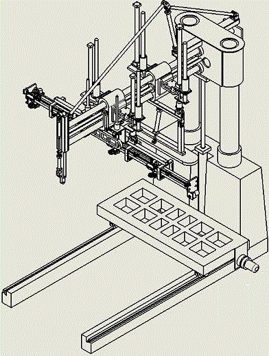
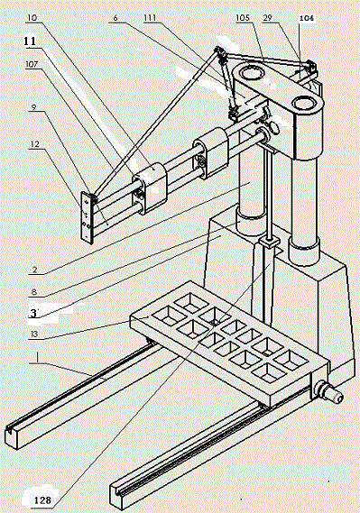
[0032]The frame in this device consists of a chassis that can be extended into the fork of a forklift. Two chrome-plated columns are fixed and welded to the chassis. The liftable beam is fixed on the flat seat of the column sliding sleeve and connected with the hydraulic cylinder to realize lifting. The movement of the column; the column sliding sleeve is composed of the inner copper sleeve and the outer fixed sleeve; the column sleeve is connected with the bottom plate of the beam seat and the beam.

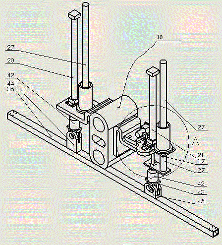
[0033] The liftable crossbeam consists of two chrome-plated optical shafts installed in the horizontal direction, an automatically adjustable triangular cable stay composed of two pull irons and hydraulic cylinders, a front end plate and a rear end plate, two movable with adjustable copper The cutting machine frame and the manipulator seat of the sliding sleeve are respectively driven by the motor to reduce the speed reducer and the screw mandrel.

[0034] Automatic cali...


PUM


Abstract

An automatic stone unloader comprises an automatic slabstone relative-parallelism adjuster, an automatic large-grooving-parallelism adjuster, a frame, a cutting device, a clamp, a vacuum sucker and a bogie. The relative position of a crossbeam and stone can be adjusted by ascending and descending of the frame, the cutting device can cut a scar deep in 3-5mm at the joint of slabstone and stone, the slabstone can move forwardly and backwardly by the aid of the clamp with the vacuum sucker, the motion distance is + / -15mm, the scar at the joint of the slabstone and the stone can be separated, a manipulator with the vacuum sucker can suck the slabstone have separated from the stone, and after rising 50mm, the slabstone is leveled and moved to the upper side of the bogie and laid down. The automatic stone unloader has the advantages of small occupation space, full automation and high efficiency and safety, and can move optionally according to production needs.

Description

technical field [0001] The invention relates to an automatic unloading device for stone materials. Background technique [0002] The format of the existing unloading machine is: the stones cut by the large cutting machine are placed on the trolley of the unloading machine. After the hydraulic cylinders on the four corners of the trolley are adjusted to the level, the stepping motor feeds the material to the specified position. The chisel on the machine strikes the connection between the stone slab and the stone, and then the impact equipment of the machine hits the stone slab to break the connection between the stone slab and the stone. On the transfer belt on the machine table, it is sent upward by the transfer belt, and after the stone slab is in a horizontal position, push the slate to the raised lifting frame in place. [0003] At present, most of the existing stone automatic unloading devices on the market are frequently replaced by wearing parts, which tak...

Claims


Application Information

Patent Timeline
Patent Type & Authority Applications(China)
IPC IPC(8): B28D1/00B28D1/22B28D7/00
CPCB28D1/00B28D1/226B28D7/00
Inventor 曾华东
Owner 曾华东
Learn More