Block injection molding equipment and injection molding method thereof

A technology of injection molding equipment and blocks, which is applied in the field of building material production, can solve the problems of energy consumption, uneven surface, low output, etc., and achieve the effect of improving the molding effect

Inactive Publication Date: 2017-09-08
王长河
View PDF1 Cites 0 Cited by
  • Summary
  • Abstract
  • Description
  • Claims
  • Application Information

AI Technical Summary

Problems solved by technology

[0002] At present, in the field of construction, the outer wall or inner wall usually adopts the masonry structure of blocks (also called bricklaying), and the masonry is mostly fly ash plus blocks, which not only wastes and consumes energy, but also has Insufficient thermal insulation, light weight, heat insulation, sound insulation performance, etc., can not meet the requirements of the national building energy conservation. In order to solve the above problems, the hollow blocks are usually treated as follows: 1. Polystyrene board or polyurethane board Cut small pieces with thermal fuses and insert them manually into the holes of the hollow blocks. This method is costly, labor-intensive, and has poor thermal insulation performance. The small blocks of benzene or polyurethane are very regular square, so there must be gaps around them, as long as there are gaps, air circulation will be generated to reduce the heat insulation function; High labor intensity, low output, uneven surface, high dry density, which will cause waste of steel bars in frame structure design; During masonry, the entire concrete protective layer is hung outside the structural column by the polystyrene board, and it is difficult to ensure that the concrete protective layer will not fall off when the polystyrene board degrades, causing accidents; 4. To the hollow block Lightweight materials such as polystyrene particles or polyurethane particles are injected into the holes. In this patent, polystyrene particles are used as an example. This method can better solve the above problems, but most of them are artificially filled with polystyrene particles. In the hole of the block, and then pass high-temperature steam into the hole of the block, the efficiency is low, the foaming is poor, and the heat preservation effect is not ideal
The patent application number 201310401916.3 discloses a block injection molding machine and its use method. In this patent, steam is injected into the completely closed space formed by the steam delivery head, the fixed mold box and the lower template through the steam pipeline through the steam delivery head. The steam instantly penetrates into the hole of the block with polyphenylene particles, making the polyphenylene particles pre-expanded and enlarged again (because the hole space of the block remains unchanged, the polystyrene particles are extruded and condensed) and condense together to form a whole with the block. Using this kind of steam entraining device, during the process of entraining, the polyphenylene particles in the upper layer of the block hole first contact with the steam and become larger instantly, making it difficult for the steam to enter the bottom layer of the block hole, resulting in the polyphenylene particles in the bottom layer of the block hole It is difficult for the particles to re-foam and become larger, and there are large gaps between the polystyrene particles, which makes it difficult for the processed blocks to achieve better thermal insulation effects; in this patent, the aggregate lower silo does not directly feed the blocks, However, the feeding of the distribution vehicle is required, and the distribution vehicle needs to move back and forth on the track, so that the whole process of block injection molding cannot be carried out sequentially on the track, and the injection molding efficiency is low.

Method used


Image

  • Block injection molding equipment and injection molding method thereof
  • Block injection molding equipment and injection molding method thereof
  • Block injection molding equipment and injection molding method thereof

Examples


specific Embodiment approach 2

[0081] like Figure 8 As shown, the gas storage box 10 is driven by the power device A, the moving frame 3 is driven by the driving device B, the gas filling needle 7 can move up and down through the gas storage box 10, the power device A and the gas storage The box 10 is connected, and the power unit B is connected with the mobile frame 3. Both the power unit A and the power unit B can be hydraulic cylinders, cylinders or electric push rods. In this embodiment, the power unit A and the power unit B are cylinders 2, the mobile frame 3 and the gas storage box 10 move up and down along the guide column 5, the mobile frame 3 is fixedly connected with the gas storage pipe 16, and the gas filling needle 7 is connected to the storage tank through the rigid connection pipe 6. The trachea 16 is connected. When adding air, the air filling needle 7 and the air storage box 10 are driven up and down by the power unit A and the power unit B respectively.

specific Embodiment approach 3

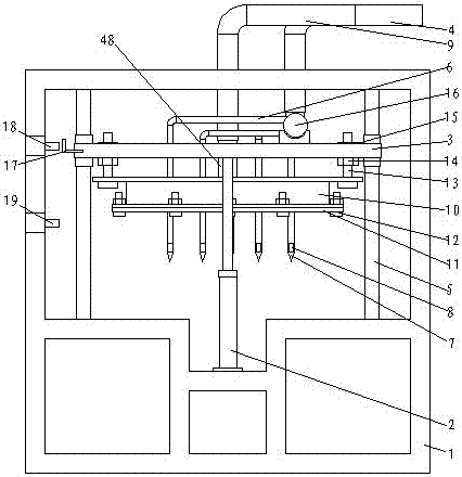
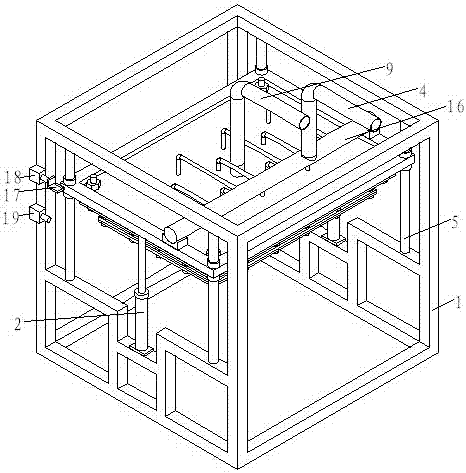
[0083] like Figure 9 As shown, the gas storage box 10 and the mobile frame 3 are fixedly connected, the gas storage box 10 and the mobile frame 3 move up and down under the drive of the power device, the gas filling needle 7 penetrates the gas storage box, and the gas filling needle 7 7 does not communicate with the gas storage box 10, the gas storage box 10 communicates with the steam source through the rigid connecting pipe 48 and the flexible connecting pipe 9, the gas filling needle 7 is connected with the gas storage pipe 16 through the rigid connecting pipe 6, and the The gas storage pipe 16 is fixed on the mobile frame 3 , and the gas storage pipe 16 communicates with the steam source through the flexible connecting pipe 4 . When adding air, the power device makes the rubber plate 11 connected to the bottom of the air storage box 10 press on the block, and at the same time, the air-filling needle 7 is inserted into the polystyrene particles in the hole of the block, an...

specific Embodiment approach 4

[0085] like Figure 10As shown, the gas filling needle 7 communicates with the gas storage box 10 and is fixedly connected with the gas storage box 10. The gas storage box 10 can move up and down along the guide column 5 under the drive of the power device. The tank 10 is connected to a steam source through a rigid connection pipe 48 and a flexible connection pipe 9 . When adding gas, the rubber plate 11 connected to the bottom of the gas storage box 10 is pressed on the block, and the gas filling needle 7 is inserted into the inside of the polystyrene particles in the hole of the block, and the gas filling needle 7 and the gas storage box 10 are simultaneously injected into the block. Introduce high temperature steam. In this embodiment, the limit switch includes two upper and lower photoelectric sensors 18 and 19 fixed on the frame and a baffle I17 fixed on the gas storage box 10 and cooperating with the photoelectric sensors 18 and 19 to precisely control The upward and d...


PUM


Abstract

The invention relates to building block injection molding equipment, which comprises a gas filling machine, wherein the gas filling machine comprises a gas filling machine rack, a gas filling device which is driven by a power device I to move up and down is arranged on the gas filling machine rack, and the gas filling device comprises a building block hole interior gas filling device and a building block hole upper surface gas filling device. The building block injection molding equipment is provided with the interior gas filling device and the upper surface gas filling device, polyphenyl granules expand, and are adhered and cured due to influence of steam, so as to form integral polyphenyl blocks matching exactly with walls of building blocks, the interior gas filling device can be used for inflating high-temperature steam into the polyphenyl granules of the building block holes, so that the polyphenyl granules in the middle and at the bottom of the building block holes are well expanded, adhered and cured, the upper surfaces of the polyphenyl granules of the building block holes can be filled with gas and pressurized through the upper surface gas filling device, so that the upper-layer polyphenyl granules of the building block holes can be well expanded, adhered and cured, the forming plane is smooth, and the heat-preservation and insulation effects of building blocks can be effectively enhanced.

Description

technical field [0001] The utility model relates to the technical field of building material production, in particular to block injection molding equipment. Background technique [0002] At present, in the field of construction, the outer wall or inner wall usually adopts the masonry structure of blocks (also called bricklaying), and the masonry is mostly fly ash plus blocks, which not only wastes and consumes energy, but also has Insufficient thermal insulation, light weight, heat insulation, sound insulation performance, etc., can not meet the requirements of the national building energy conservation. In order to solve the above problems, the hollow blocks are usually treated as follows: 1. Polystyrene board or polyurethane board Cut small pieces with thermal fuses and insert them manually into the holes of the hollow blocks. This method is costly, labor-intensive, and has poor thermal insulation performance. The small blocks of benzene or polyurethane are very regular sq...

Claims


Application Information

Patent Timeline
Patent Type & Authority Patents(China)
IPC IPC(8): B29C45/03B29C45/17
CPCB29C44/12B29C44/3426B29C44/35B29C44/40
Inventor 王长河
Owner 王长河
Why Eureka
Try Eureka