
Electric car frame structure for distributed installation of battery packs

A technology of electric vehicle and frame structure, which is applied in the substructure, electric power unit, transportation and packaging, etc., can solve the problem that the integrity and safety performance of battery cells cannot be guaranteed, the overall quality of the frame and battery pack structure is large, and it is difficult to Battery pack safety performance protection and other issues, achieve excellent machining performance and casting process performance, achieve lightweight design, and reduce natural phenomena

Active Publication Date: 2015-03-25
HUNAN UNIV
View PDF4 Cites 56 Cited by
  • Summary
  • Abstract
  • Description
  • Claims
  • Application Information

AI Technical Summary

Problems solved by technology

[0003] However, the battery pack structure and frame structure of current mainstream electric vehicles often adopt an independent design strategy. The disadvantage is that the overall mass of the electric vehicle frame and battery pack structure is very large, and it is difficult to fully guarantee the safety performance of the battery pack. Azimuth protection
As a result, the structure of the battery pack cannot guarantee the integrity and safety performance of the battery cells during the long-term work or collision accident of the electric vehicle, so the battery cells are easy to squeeze each other, causing battery damage, battery spontaneous combustion, etc.

Method used


Image

  • Electric car frame structure for distributed installation of battery packs
  • Electric car frame structure for distributed installation of battery packs
  • Electric car frame structure for distributed installation of battery packs

Examples


Embodiment Construction

[0045] The present invention will be described in further detail below in conjunction with the accompanying drawings and specific embodiments.

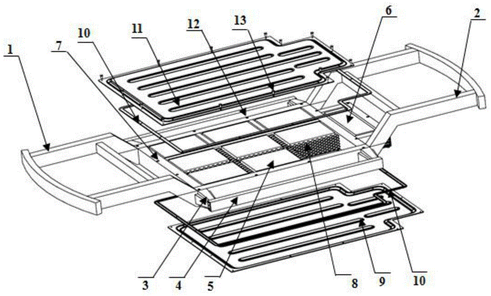
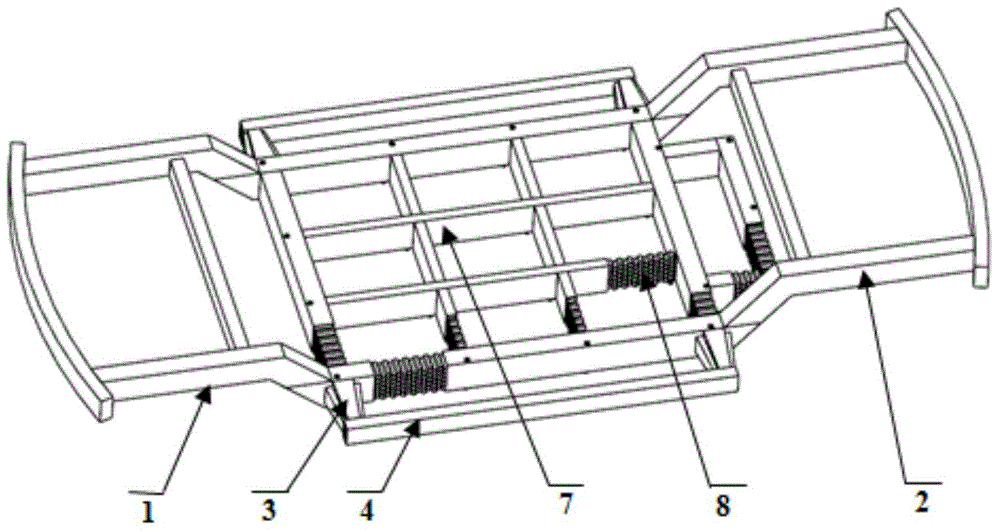
[0046] like Figure 1-2 As shown, the electric vehicle frame structure for distributed installation of battery packs according to the present invention includes four parts: a frame type frame, a block type battery pack structure, a sealing plate and a floor.

[0047] The framed frame includes a front beam 1, a rear beam 2, a tapered multicellular thin-walled tube structure 3 and a sill structure 4; wherein, the front frame 1 is located at the front end of the framed frame, and the rear frame The frame 2 is located at the rear of the frame type frame, the front frame 1 and the rear frame 2 are connected through the longitudinal energy-absorbing structures located on the left and right sides of the orthogonal energy-absorbing structure 7, and the threshold structure 4 is connected with the orthogonal energy-absorbing structure 7. The e...


PUM


Abstract

The invention provides an electric car frame structure for distributed installation of battery packs. The electric car frame structure comprises a framework type car frame, a block-based battery pack structure, a sealing board and a floor, wherein the framework type car frame comprises a front car beam (1), a rear car beam (2), a conical multi-cell thin-wall pipe structure (3) and a threshold structure (4); the front car beam (1) is located at the front end of the framework type car frame, the rear car beam (2) is located at the rear portion of the framework type car frame, the front car beam (1) and the rear car beam (2) are connected through longitudinal energy absorption structures on the left side and the right side in an orthometric energy absorption structure (7), and the threshold structure (4) and the orthometric energy absorption structure (7) are in transitional connection through the conical multi-cell thin-wall pipe structure. The implementation mode is easy, convenient and fast, the number of parts is decreased, the utilization rate of materials is improved, the manufacturing process of the integrated structure is simplified, the structure lightweight design is achieved, and meanwhile the crash safety performance is improved to a great extent.

Description

technical field [0001] The invention relates to an electric vehicle frame structure for distributed installation of battery packs, in particular to an electric vehicle frame structure capable of efficiently absorbing energy, comprehensively protecting battery pack collision safety performance, and having a high degree of light weight. Background technique [0002] The rapid development of the automobile industry is facing a series of bottlenecks such as energy shortage and environmental pollution. Safety, energy saving and environmental protection have become the themes of the development of the automobile industry. To achieve this goal, the development of electric vehicles has become an inevitable trend. However, the main factors restricting the rapid development of electric vehicles are battery cruising range and battery safety issues. Since the weight of the battery pack body accounts for about one-third of the curb weight of the electric vehicle, in order to achieve the...

Claims


Application Information

Patent Timeline
IPC IPC(8): B62D21/00B62D21/15B60K1/04
CPCB60K1/04B60K2001/0438B62D21/152B62D21/157
Inventor 成艾国段利斌李光耀丁振周振李卓
Owner HUNAN UNIV
Features
  • Generate Ideas
  • Intellectual Property
  • Life Sciences
  • Materials
  • Tech Scout
  • Unparalleled Data Quality
  • Higher Quality Content
  • 60% Fewer Hallucinations
Learn More