
Rotating drum for cheese dewatering

A technology of package yarn and rotary cage, which is used in centrifugal force liquid/gas/vapor removal, textile and papermaking, textile processing machine accessories, etc., can solve the problems of high production cost, easy flattening of package yarn, and high energy consumption. , to achieve the effect of reducing moisture content and improving dehydration effect

Active Publication Date: 2015-03-25
WUXI QIANZHOU YAODA MACHINERY FACTORY
View PDF3 Cites 14 Cited by
  • Summary
  • Abstract
  • Description
  • Claims
  • Application Information

AI Technical Summary

Problems solved by technology

It can be seen that the dehydration of cheese by using the dehydrator of the above-mentioned tumbler will consume a lot of energy in the subsequent drying step and the production cost will be high.
[0003] And because of the centrifugal force during the dehydration process, one side of the cheese on each support rod is against the vertical groove wall on the inner wall of the mesh cylinder, so that the cheese is easily crushed when the dehydration is completed. , even the bobbin is deformed, and the yarns on the outer layer of the cheese are easy to stick together, making it easy to break when the subsequent yarn is rewound

Method used


Image

  • Rotating drum for cheese dewatering
  • Rotating drum for cheese dewatering
  • Rotating drum for cheese dewatering

Examples


Embodiment Construction

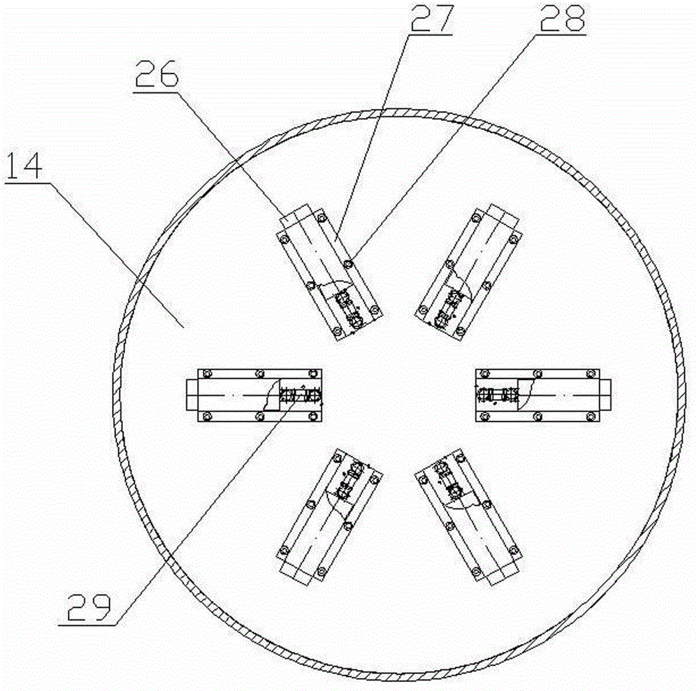
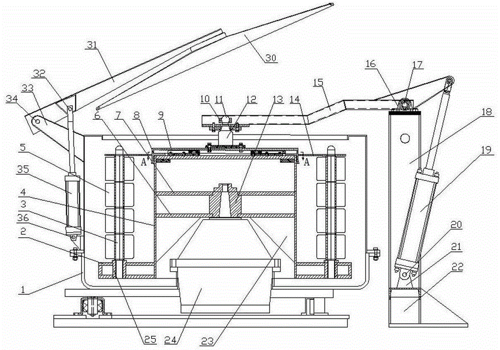
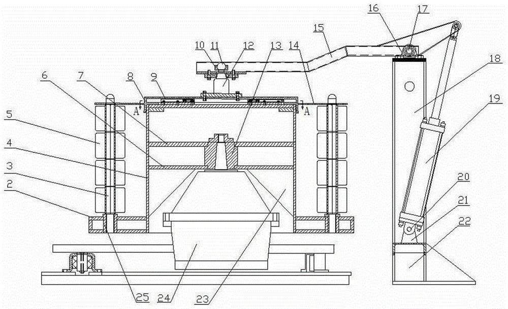
[0019] Such as figure 1 As shown, the bobbin dehydration basket of the present invention comprises a cage body, and the cage body contains a vertical tube 4, and a fixed vertical vertical tube 4 is arranged at about the middle of the height direction of the vertical tube 4 inner cavity. plate, and the periphery of the fixed plate is welded on the inner wall of the vertical cylinder 4. Be processed with central hole on the fixed plate, be provided with 24 below the fixed plate, the output shaft of motor 24 is upward and fix with nut 13 after passing the central hole on the fixed plate. An annular disk 2 is arranged at the lower end of the vertical cylinder 4 , and the inner circumference of the annular disk 2 is welded around the lower end of the vertical cylinder 4 . Vertical rod holes are evenly distributed around the circumference of the annular disk 2, and rod sleeves 25 are installed in the vertical rod holes. A gland 14 is arranged on the upper end of the vertical tube ...


PUM


Abstract

The invention relates to a rotating drum for cheese dewatering. The rotating drum comprises a drum body, wherein a vertical cylinder is arranged in the drum body, a fixing plate is arranged approximately in the middle of an inner cavity of the vertical cylinder in the height direction, a motor is arranged below the fixing plate, and an output shaft of the motor is fixedly connected with the fixing plate. The rotating drum is characterized in that an annular disc is connected to the lower end of the vertical cylinder, vertical rod holes are evenly distributed in the circumference of the annular disc, a gland is arranged at the upper end of the vertical cylinder, the diameter of the gland is larger than the length of the line connecting the outer sides of two corresponding rod holes located on the same diameter line, rod holes are evenly distributed in the circumference of the gland and correspond to the rod holes in the annular disc, supporting rods are evenly distributed between the circumference of the annular disc and the circumference of the gland, and the upper ends and lower ends of the supporting rods stretch into the corresponding rod holes in the annular disc and the gland. When a dewaterer provided with the rotating drum is used for dewatering cheese, dewatering effect is good, energy consumption is low during later drying, production cost is low, the situations that cheese is pressed flat, yarns are bonded together and yarn breaking occurs during yarn rewinding can be avoided, and deformation of a bobbin is avoided. The rotating drum is suitable for dewatering after a yarn roll is dyed.

Description

technical field [0001] The invention relates to a dehydrator. Specifically, it is a tumbler on a dehydration machine for dehydrating dyed yarn rolls, especially suitable for dehydrating dyed cheese packages. Background technique [0002] At present, in the printing and dyeing industry, the dehydrator used to dehydrate the dyed package mainly consists of a casing and a rotating cage arranged in the casing. The rotating cage wherein comprises a cage body, and the cage body contains a vertical cylinder and a net cylinder, and glands are arranged on the upper ends of the vertical cylinder and the net cylinder. The height of the inner cavity of the vertical cylinder is fixed with a fixed plate perpendicular to the vertical direction of the vertical cylinder in the middle of the height of the vertical cylinder. A motor is arranged below the fixed plate, and the output shaft of the motor faces upward and is fixedly connected with the fixed plate. The lower end of the mesh cylinde...

Claims


Application Information

Patent Timeline
IPC IPC(8): D06B23/00D06B23/04D06B15/10
CPCD06B15/10D06B23/00D06B23/04
Inventor 余耀平余育强
Owner WUXI QIANZHOU YAODA MACHINERY FACTORY
Learn More