Bubble eliminating device for cast-in-place concrete piles

A technology for eliminating air bubbles and pouring piles, which is applied to sheet pile walls, construction, infrastructure engineering, etc., can solve problems such as difficulty in vibrating, inaccessibility of vibrating rods, and poor effect.

Inactive Publication Date: 2015-03-25
广东华兴达岩土工程有限公司
View PDF3 Cites 0 Cited by
  • Summary
  • Abstract
  • Description
  • Claims
  • Application Information

AI Technical Summary

Problems solved by technology

However, the concrete pouring piles that adopt the drilling process also have their defects: the quality of the concrete pouring has a great influence on the bearing capacity of the piles. If air bubbles appear in the pouring process, honeycombs will be formed on the pile body, and these honeycombs will seriously reduce the bearing capacity of the piles. carrying capacity
However, in the existing technology, the concrete with a relatively large slump is only used to form a pile by its own weight, and the pile body is not compacted by techniques such as vibration and mixing. This is because the vibration and mixing of concrete pouring piles have objective difficulties. First of all, the pile length of cast-in-situ piles is generally more than ten meters to tens of meters, and the vibrating rod cannot reach such a deep depth at all. If the condition is inside, it is difficult to vibrate and the effect is not good

Method used


Image

  • Bubble eliminating device for cast-in-place concrete piles
  • Bubble eliminating device for cast-in-place concrete piles
  • Bubble eliminating device for cast-in-place concrete piles

Examples


Embodiment Construction

[0027] Embodiments of the present invention will be described in further detail below in conjunction with the accompanying drawings.

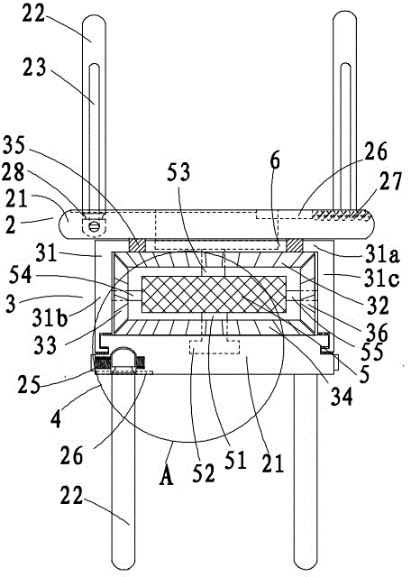
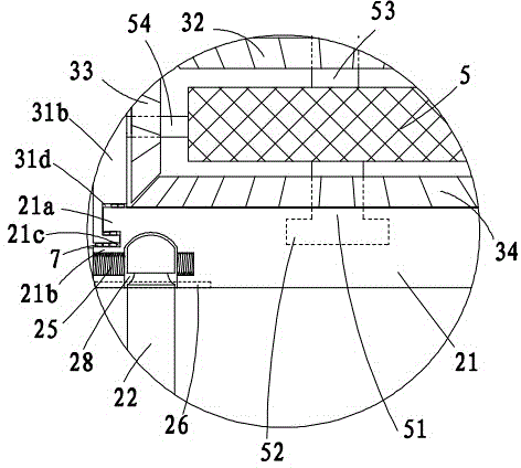
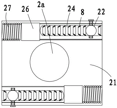
[0028] Figure 1 to Figure 14 Shown is the structural representation of the present invention.

[0029] The reference signs therein are: pouring pipe 1, discharge hole 11, upper layer stirring device 2, upper plate center hole 2a, rotating plate 21, first ring protrusion 21a, second ring protrusion 21b, plate side groove 21c, stirring column 22. Sliding groove 23, adjusting groove 24, fixing hole 25, push plate 26, push spring 27, clamping ring groove 28, middle transmission structure 3, transmission bracket 31, top bracket plate 31a, left side bracket plate 31b, right Side support plate 31c, annular groove 31d, top helical gear 32, left helical gear 33, bottom helical gear 34, connecting column 35, right helical gear 36, bottom stirring device 4, motor 5, transmission shaft 51, shaft head convex 52, upper motor fixed mount 53, left motor fix...


PUM


Abstract

The invention discloses a bubble eliminating device for cast-in-place concrete piles. The bubble eliminating device has the advantages that an upper-layer stirring device and a bottom-layer stirring device can be driven by an intermediate-layer transmission structure to rotate in the identical directions or reverse directions, and the extending lengths of stirring columns can be adjusted by the upper-layer stirring device and the bottom-layer stirring device according to the diameters of pile holes, so that a cast-in-place concrete pile pouring machine is applicable to the cast-in-place piles with different pile diameters, and the bubble eliminating device can rise up or drop down along with a pouring pipe and is convenient to use; annular grooves in the bottoms of side support plates and lower plate-side grooves in lower rotary plates can be clamped in one another, so that the lower rotary plates can be limited in the vertical directions by the side support plates, horizontal joints of each side support plate and the corresponding lower rotary plate are provided with seal floating rings to form three seals, accordingly, mortar and water can be effectively stopped from being permeated into a hollow cavity of a transmission support, and normal running of a motor can be guaranteed.

Description

technical field [0001] The invention relates to the technical field of civil engineering, in particular to a device for eliminating air bubbles of concrete pouring piles. Background technique [0002] The cast-in-situ concrete pile is a kind of pile formed by directly forming a hole on the spot pile position, and then pouring concrete in the hole or placing a steel cage and then pouring concrete. The characteristic is that the pile diameter can be selected according to the needs, and piles with a diameter much larger than that of prefabricated piles can be built. Compared with the hammering method in sinking piles, the construction noise and vibration are much smaller, and it can be applied to various foundations. There are generally two types of existing concrete cast-in-place piles: immersed tube cast-in-place piles and bored cast-in-place piles. Among them, immersed tube cast-in-place piles use hammering pile sinking equipment to sink tubes and pull out tubes to form pile...

Claims


Application Information

Patent Timeline
Patent Type & Authority Applications(China)
IPC IPC(8): E02D15/04
CPCE02D5/46E02D15/04
Inventor 肖强王洪伟
Owner 广东华兴达岩土工程有限公司
Why Eureka
Try Eureka