Exhaust gas injection mechanism

A technology of exhaust gas and ejector tubes, which is applied in the direction of exhaust devices, mechanical equipment, engine components, etc., and can solve problems such as dust extraction, poor cooling effect, and insufficient negative pressure

Active Publication Date: 2015-03-25
WUXI WEIFU LIDA CATALYTIC CONVERTER
View PDF7 Cites 0 Cited by
  • Summary
  • Abstract
  • Description
  • Claims
  • Application Information

AI Technical Summary

Problems solved by technology

[0003] In view of the above problems, the present invention provides an exhaust gas injection mechanism, which is installed in the catalytic converter of the exhaust gas post-treatment system, which solves the problem of insufficient negative pressure, dust extraction, and poor cooling effect during conventional waste injection work. and other defects

Method used


Image

  • Exhaust gas injection mechanism
  • Exhaust gas injection mechanism
  • Exhaust gas injection mechanism

Examples


Embodiment Construction

[0016] The specific embodiments of the present invention will be further described below in conjunction with the accompanying drawings.

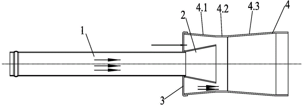
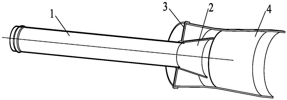
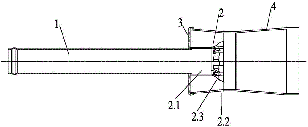
[0017] Figure 1~7 Among them, it includes injection tube 1, expansion guide cylinder 2, cylindrical section 2.1, petal section 2.2, raised air groove 2.3, fixed ring 3, outer tube 4, contraction section 4.1, stabilization section 4.2, expansion section 4.3, etc.

[0018] Such as Figure 1~7 As shown, the present invention is an exhaust gas injection mechanism, which includes an outer pipe 4 whose gas outlet is connected to the housing of the catalytic converter. Connected, the outlet end of the injection tube 1 is connected with an expansion guide cylinder 2, the expansion guide cylinder 2 is placed in the outer tube 4, and the axes of the expansion guide cylinder 2 and the outer tube 4 coincide; the expansion guide The diameter of the air outlet of the tube 2 is greater than that of the air inlet, the surface of the outer tube 4 is a smo...


PUM


Abstract

The invention relates to the field of automotive exhaust purification processing, in particular to an exhaust gas injection mechanism. The exhaust gas injection mechanism comprises an outer pipe with the exhaust gas outlet end connected with a catalytic purifier shell. The gas inlet end of the outer pipe is connected with the gas outlet end of an injection pipe through a fixing ring. The gas outlet end of the injection pipe is connected with an expansion guide barrel arranged in the outer pipe. The axis of the expansion guide barrel coincides with the axis of the outer pipe. The diameter of a gas outlet of the expansion guide barrel is larger than the diameter of a gas inlet of the expansion guide barrel. The surface of the outer pipe is of a smooth circular arc transition structure. The inner diameter of the two ends of the circular arc transition structure is larger than the inner diameter of the middle section of the circular arc transition structure. The injection mechanism is installed in a catalytic purifier of an exhaust after-treatment system, and the defects that the negative pressure is insufficient, and the dust exhausting effect and the cooling effect are poor during conventional exhaust gas injection are overcome.

Description

technical field [0001] The invention relates to the field of automobile tail gas purification treatment, in particular to an exhaust gas injection mechanism. Background technique [0002] The exhaust gas injection device ejects the cold air in the external environment by means of the kinetic energy of the high-temperature and high-speed airflow discharged from the engine to form a negative pressure, thereby achieving the purposes of dust extraction, cooling, and noise reduction. When the car is working in a dusty environment, if the dust in the air filter is not discharged in time, the filter element will be blocked, and in severe cases, it will cause insufficient air supply, causing problems such as flameout under heavy load. Contents of the invention [0003] In view of the above problems, the present invention provides an exhaust gas injection mechanism, which is installed in the catalytic converter of the exhaust gas post-treatment system, which solves the problem of i...

Claims


Application Information

Patent Timeline
Patent Type & Authority Applications(China)
IPC IPC(8): F01N3/05F01N3/28
Inventor 袁可平何伟娇
Owner WUXI WEIFU LIDA CATALYTIC CONVERTER
Why Eureka
Try Eureka