Connecting rod and cam type pressure adjusting device

A pressure adjustment, connecting rod cam technology, applied in valve device, valve operation/release device, valve details, etc., can solve problems such as difficulty in modification, and achieve the effect of simple structure, convenient installation and cost saving

Inactive Publication Date: 2015-03-25
重庆市明皓光学仪器有限公司
View PDF3 Cites 2 Cited by
  • Summary
  • Abstract
  • Description
  • Claims
  • Application Information

AI Technical Summary

Problems solved by technology

But in actual application, when the installation of the water supply system has been completed,...

Method used


Image

  • Connecting rod and cam type pressure adjusting device

Examples


Embodiment Construction

[0011] Below in conjunction with accompanying drawing and specific embodiment the present invention will be described in further detail:

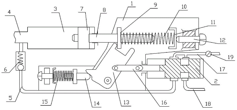
[0012] The reference signs in the drawings of the description include: support plate 1, slide valve 2, servo hydraulic cylinder 3, liquid delivery pipeline 4, conduit 5, gate valve 6, piston 7, piston rod 8, annular protrusion 9, coil spring 10 , Deck 11, screw 12, cam 13, push rod 14, compression spring 15, pole 16, water inlet pipe 17, water outlet pipe 18, throttle valve 19.

[0013] Such as figure 1 As shown, the connecting rod cam type pressure regulating device includes a support plate 1, a slide valve 2, a servo hydraulic cylinder 3 and a liquid delivery pipe 4 connected to the servo hydraulic cylinder 3, the liquid delivery pipe 4 is connected with a conduit 5, and the conduit 5 is provided with The gate valve 6 and the servo hydraulic cylinder 3 include a piston 7 and a piston rod 8 connected to the piston 7. The piston rod 8 is p...


PUM


Abstract

The invention discloses a connecting rod and cam type pressure adjusting device. The connecting rod and cam type pressure adjusting device comprises a supporting plate, a sliding valve, a servo hydraulic cylinder and a liquid conveying pipeline communicated with the servo hydraulic cylinder. The liquid conveying pipeline is communicated with a guide pipe. A sluice valve is arranged on the guide pipe. The servo hydraulic cylinder comprises a piston and a piston rod connected with the piston. The piston rod is provided with an annular protrusion and sleeved with a spiral spring. A clamping seat is arranged on the outer side of the piston rod and fixed to the supporting plate. The clamping seat and the piston rod are located on the same horizontal line. One end of the spiral spring is connected with the annular protrusion. The other end of the spiral spring is connected with the clamping seat. A cam hinged to the supporting plate is arranged below the annular protrusion and connected with a push rod capable of moving horizontally. The connecting rod and cam type pressure adjusting device is easy to install, and an existing system does not need to be largely transformed.

Description

technical field [0001] The invention relates to a pressure regulator capable of automatically adjusting water pressure and air pressure, in particular to a connecting rod cam type pressure regulator. Background technique [0002] In the existing liquid or gas delivery systems, most of the connections between the ends and specific appliances do not have pressure regulating devices. Such as the connection between the faucet and the water pipe, the connection between the air pump and the air pressure nail gun, etc. Taking tap water as an example, the connections between tap water pipes and between water pipes and faucets are all realized through joints. At present, these joints are mainly used for connection and do not have other functions. There are generally two ways to supply water to buildings at present, one is to use a booster pump to send water from bottom to top, and the other is to place a water tank on the roof and use the water level difference to transport water fr...

Claims


Application Information

Patent Timeline
IPC IPC(8): F16K31/524
CPCF16K31/52475
Inventor 谢吉阳
Owner 重庆市明皓光学仪器有限公司
Why Eureka
Try Eureka