Eureka AIR delivers breakthrough ideas for toughest innovation challenges, trusted by R&D personnel around the world.

Dual-purpose air humidifier

An air humidifier and dual-purpose technology, applied in the field of industrial machinery, can solve the problems of inability to dry the air, and achieve the effects of saving water, saving space, and being easy to control.

Inactive Publication Date: 2015-03-25
上海伟阳纸业有限公司
View PDF1 Cites 2 Cited by
  • Summary
  • Abstract
  • Description
  • Claims
  • Application Information

AI Technical Summary

Problems solved by technology

[0002] An air humidifier is a device that increases the water vapor content in the air. It is a household appliance that increases the humidity of a room. The humidifier can humidify a designated room, or it can be connected to a boiler or a central air-conditioning system to humidify the entire building. According to the theory of heat and humidity exchange , In actual engineering, humidifiers are divided into the following two types: isenthalpy humidifier and isothermal humidifier. Isenthalpy humidifier is to use water to absorb the sensible heat of air for evaporative humidification. The change on the graph is an approximately isenthalpic process, that is, the use of thermal energy to convert liquid water into steam and mix it with air for humidification. The change on the enthalpy and humidity chart is an approximately isothermal process. The application number is 200610065844.X, which discloses an air humidifier , including a machine box, a water storage tank, and an ultrasonic transducer, which are used to generate water vapor in a vertical pipe connected to the opening of the machine box by vibrating the water in the water storage tank. Aroma distributing device, wherein, the aroma distributing device has an elongated inner tank, which is made of a porous material and can absorb volatile fragrances. This air humidifier does not play the role of air drying

Method used


Image

  • Dual-purpose air humidifier
  • Dual-purpose air humidifier

Examples


Embodiment Construction

[0013] In order to make the technical means, creative features, goals and effects achieved by the present invention easy to understand, the present invention will be further described below in conjunction with specific embodiments.

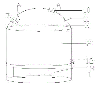
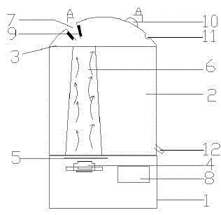
[0014] Such as figure 1 and 2 As shown, a dual-purpose air humidifier includes a housing 1, the housing 1 is provided with a water storage bin 2, the water storage bin 2 is provided with a humidification cover 3, and the housing 1 is provided with a blower 4 and a vaporizer filter 5, the water storage bin 2 is provided with a mist guide chamber 6, the humidification cover 3 is provided with an air outlet 7, the mist guide chamber 6 is in communication with the air outlet 7, and the housing 1 is also provided with Drying drive device 8, the air outlet 7 is a sheet-like inverted V shape, and the air outlet 7 is provided with a condensation sheet 9. This setting adds the function of the dryer to the air humidifier. When the weather is dry, the humi...


PUM


Abstract

The invention discloses a dual-purpose air humidifier, and relates to the field of industrial machinery. The dual-purpose air humidifier comprises a shell, a water storage bin and a humidifying cover, wherein the water storage bin is arranged on the shell, and is provided with the humidifying cover; an air blower and a gasifying filter are arranged in the shell; a mist guide chamber is formed in the water storage bin; an air outlet is formed in the humidifying cover; the mist guide chamber is communicated with an air flow of the air outlet; a drying driving device is additionally arranged in the shell; the air outlet takes the shape of a piece type inverted V, and is provided with a condensing piece; and the condensing piece is electrically connected with the drying driving device. Through the settings, the functions of a dryer are added into the air humidifier; when the weather is dry, the humidifying function is opened; when the weather is too moist, the drying function is opened; and the conversion of the humidifying and drying functions can save the water source.

Description

technical field [0001] The invention relates to the field of industrial machinery, in particular to a dual-purpose air humidifier. Background technique [0002] An air humidifier is a device that increases the water vapor content in the air. It is a household appliance that increases the humidity of a room. The humidifier can humidify a designated room, or it can be connected to a boiler or a central air-conditioning system to humidify the entire building. According to the theory of heat and humidity exchange , In actual engineering, humidifiers are divided into the following two types: isenthalpy humidifier and isothermal humidifier. Isenthalpy humidifier is to use water to absorb the sensible heat of air for evaporative humidification. The change on the graph is an approximately isenthalpic process, that is, the use of thermal energy to convert liquid water into steam and mix it with air for humidification. The change on the enthalpy and humidity chart is an approximately ...

Claims


Application Information

Patent Timeline
IPC IPC(8): F24F6/12B01D53/26B01D53/00
CPCF24F6/12B01D53/265
Inventor 简文秀
Owner 上海伟阳纸业有限公司
Why Eureka
Eureka Blog
Learn More