
Drying and dispersing device for wet powder materials

A drying and wet powder technology, applied in the direction of drying solid materials, drying gas arrangement, drying, etc., can solve the problems of affecting the dryness of powder materials, easy agglomeration of wet powder materials, and unfavorable complete drying, etc., to achieve low cost and dry Good performance and improved dispersibility

Active Publication Date: 2015-03-25
江苏雄风科技有限公司
View PDF3 Cites 14 Cited by
  • Summary
  • Abstract
  • Description
  • Claims
  • Application Information

AI Technical Summary

Problems solved by technology

However, when the airflow dryer is used to dry wet powder, because the wet powder is easy to agglomerate, it is not conducive to being completely dried during the working process, which not only affects the dryness of the powder, but also is not conducive to being airflow It is carried away and enriched in the drying cylinder, which eventually leads to tower blockage and even fire accidents

Method used


Image

  • Drying and dispersing device for wet powder materials
  • Drying and dispersing device for wet powder materials

Examples


Embodiment 1

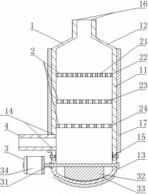
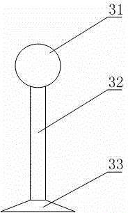
[0017] Such as figure 1 As shown, the drying and dispersing equipment for wet powder includes a drying cylinder 1, a plurality of sieve plates 2 and an anti-sedimentation rotating assembly 3. The drying cylinder 1 includes a cylinder body 11 with openings at both upper and lower The top cover 12 on the upper end surface of the body 11 and the cylinder bottom 13 fixedly connected to the lower end surface of the cylinder body 11, the lower part of the side wall of the cylinder body 11 is provided with a feed port 14 penetrating through the inner and outer walls of the side wall, and the top cover 12 is provided with a The discharge port 16 on the end face, the anti-sinking rotating assembly 3 includes a rotating rod 31 that can rotate along the axis, a connecting plate 32 that is fixedly connected to the circumferential surface of the rotating rod 31, a scraper 33 that is fixedly connected to the lower end surface of the connecting plate 32, and a driving Rotating rod 31 rotates...

Embodiment 2

[0020] This embodiment makes the following further limitations on the basis of Example 1: the sieve plate 2 includes an upper sieve plate 22, a middle sieve plate 23, and a lower sieve plate 24 distributed longitudinally from top to bottom, and the lower sieve plate 24 Located above the feed port 14. In this embodiment, the lower sieve plate 24 is located above the feed port 14, so that the agglomerated wet material deposited on the cylinder bottom 13 can be dried by the hot air at the feed port 14 through the anti-sedimentation rotating assembly 3 and move upward with the air flow.

Embodiment 3

[0022] In this embodiment, on the basis of Embodiment 1, further limitations are made as follows: among the plurality of sieve plates 2 , the distance between every two adjacent sieve plates 2 gradually decreases from top to bottom. In this example, because the aperture diameter of the upper sieve hole 21 of the middle sieve plate 23 is larger than that of the upper sieve hole 21 of the upper sieve plate 22, the material is easy to pass through the middle sieve plate 23 under the action of the hot air flow and the induced draft fan air flow but not easy to pass through the upper sieve plate 22. Sieve plate 22. At this time, the material tends to stay in the area between the middle sieve plate 23 and the upper sieve plate 22. In order to avoid clogging, the distance between the lower sieve plate 24 and the middle sieve plate 23 is smaller than the distance between the middle sieve plate 22 and the upper sieve plate 22. .


PUM


Abstract

The invention discloses a drying and dispersing device for wet powder materials. The device comprises a drying cylinder, multiple screening plates and an anti-settling rotary assembly. The drying cylinder comprises a cylinder body, a top cover and a cylinder bottom, a feed inlet is formed in the lower portion of the side wall of the cylinder body, and a discharging opening is formed in the top cover. The anti-settling rotary assembly comprises a rotary rod, a connecting plate, a scraper and a rotation driving element, the rotary rod penetrates through the cylinder body or the two side walls of the cylinder bottom and is arranged below the feed inlet, the rotation driving element is fixedly connected with the end of the rotary rod and arranged on the outer side of the cylinder body or the outer side of the cylinder bottom, the lower end face of the connecting plate are matched with the upper end face of the cylinder bottom, the screening plates are transversely arranged in the cylinder body and are longitudinally distributed along the axis of the cylinder body, the screening plates are provided with a plurality of screening holes penetrating through the upper end faces and the lower end faces of the screening plates, and according to every two adjacent screening plates, the aperture of the screening holes in the lower screening plate is larger than that of the screening holes in the upper screening plate. The drying and dispersing device overcomes the defects of an existing flash dryer, and has the advantages of being good in drying performance, high in reliability and low in cost.

Description

technical field [0001] The invention relates to the field of airflow dryers, in particular to drying and dispersing equipment for wet powder materials. Background technique [0002] The airflow dryer has the advantages of high drying strength, large processing capacity, and simple equipment, and has been widely used in the pharmaceutical, food, and chemical industries. However, when the airflow dryer is used to dry wet powder, because the wet powder is easy to agglomerate, it is not conducive to being completely dried during the working process, which not only affects the dryness of the powder, but also is not conducive to being airflow It is carried away and enriched in the drying cylinder, which eventually leads to tower blockage and even fire accidents. Contents of the invention [0003] The purpose of the present invention is to overcome the deficiency of the above-mentioned existing air dryer, and to provide drying and dispersing equipment for wet powder. [0004] T...

Claims


Application Information

Patent Timeline
IPC IPC(8): F26B17/14F26B21/00F26B25/04B07B1/46
Inventor 刘军
Owner 江苏雄风科技有限公司
Features
  • Generate Ideas
  • Intellectual Property
  • Life Sciences
  • Materials
  • Tech Scout
  • Unparalleled Data Quality
  • Higher Quality Content
  • 60% Fewer Hallucinations
Learn More