
Method for synchronously measuring attenuation coefficient and cut-off wavelength of optical fiber

A technology of attenuation coefficient and test method, which is applied in the direction of testing optical performance, etc., can solve the problems of long test time, complicated process, low test efficiency, etc., and achieve the effect of shortening test time, reducing test steps and improving test efficiency

Active Publication Date: 2015-03-25
SHANGHAI SECRI OPTICAL & ELECTRIC CABLE CO LTD
View PDF7 Cites 9 Cited by
  • Summary
  • Abstract
  • Description
  • Claims
  • Application Information

AI Technical Summary

Problems solved by technology

[0003] At present, the test of fiber attenuation coefficient and cut-off wavelength is carried out separately. At the same time, there are two test methods for fiber cut-off wavelength: bending reference method and multimode reference method. Therefore, when testing fiber attenuation coefficient and cut-off wavelength, There are many test steps, the process is complicated, and the test time is too long, resulting in low test efficiency

Method used


Image

  • Method for synchronously measuring attenuation coefficient and cut-off wavelength of optical fiber
  • Method for synchronously measuring attenuation coefficient and cut-off wavelength of optical fiber
  • Method for synchronously measuring attenuation coefficient and cut-off wavelength of optical fiber

Examples


Embodiment Construction

[0043] The implementation of the present invention will be illustrated by specific specific examples below, and those skilled in the art can easily understand other advantages and effects of the present invention from the contents disclosed in this specification.

[0044] It should be noted that the structures, proportions, sizes, etc. shown in the drawings attached to this specification are only used to match the content disclosed in the specification, for those who are familiar with this technology to understand and read, and are not used to limit the implementation of the present invention. Limiting conditions, so there is no technical substantive meaning, any modification of structure, change of proportional relationship or adjustment of size, without affecting the effect and purpose of the present invention, should still fall within the scope of the present invention. The disclosed technical content must be within the scope covered. At the same time, terms such as "upper"...


PUM


Abstract

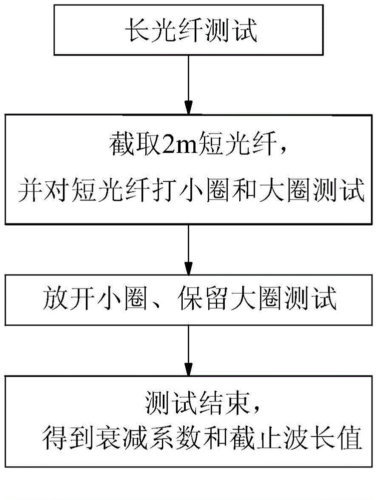
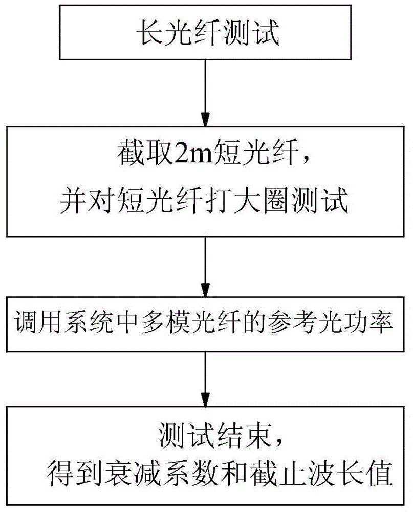
The invention provides a method for synchronously measuring the attenuation coefficient and cut-off wavelength of an optical fiber. A bending reference method or a multi-mode reference method is adopted for measuring the attenuation coefficient and cut-off wavelength of the optical fiber. The bending reference method includes the following steps of measuring the fiber output optical power of the long optical fiber to be tested, cutting out a short optical fiber, measuring the fiber output optical power of the short optical fiber in the status of a small circle and a large circle, releasing the small circle, measuring the fiber output optical power of the short optical fiber only in the status of the large circle, and working out the cut-off wavelength and the attenuation coefficient. The multi-mode reference method includes the following steps of measuring the fiber output optical power of the long optical fiber to be tested, cutting out a short optical fiber, measuring the fiber output optical power of the short optical fiber, calling the existing fiber output optical power of the output end of a multi-mode optical fiber in a system, fitting the transmission power spectrum of the short optical fiber in the status of a large circle, and working out the cut-off wavelength and the attenuation coefficient. The attenuation coefficient and cut-off wavelength of the optical fiber can be simultaneously measured through the bending reference method or the multi-mode reference method, and therefore the number of measuring steps is reduced, measuring time is shortened, and measuring efficiency is effectively improved.

Description

technical field [0001] The invention relates to a method for testing optical fiber parameters, in particular to a method for synchronously testing fiber attenuation coefficient and cut-off wavelength. Background technique [0002] Optical fiber attenuation coefficient (also known as attenuation coefficient) refers to the attenuation value of optical signal power per kilometer of optical fiber. It is one of the most important characteristic parameters of multimode optical fiber and single-mode optical fiber. The relay distance of multimode fiber optic communication. In addition, the cut-off wavelength is defined as: a single-mode fiber usually has a certain wavelength. When the wavelength of the transmitted light exceeds this wavelength, the fiber can only transmit light in one mode (fundamental mode), and below this wavelength, the fiber can Propagates light in multiple modes (including higher order modes). Therefore, in the actual application of optical fiber, it is often...

Claims


Application Information

Patent Timeline
Patent Type & Authority Applications(China)
IPC IPC(8): G01M11/02
Inventor 胡姊娟黄琦凯沈奶连涂建坤龚江疆
Owner SHANGHAI SECRI OPTICAL & ELECTRIC CABLE CO LTD
Learn More