Optical fiber fusion and distribution integrated unit disc

A fusion and optical fiber technology, applied in the field of optical fiber fusion integrated unit disk, can solve the problems of affecting the speed of fiber finding, reducing network quality, increasing optical path attenuation, etc., achieving convenient installation and disassembly, improving network quality, reducing Effects of Pigtail Redundancy

Inactive Publication Date: 2015-03-25
高文亭 +2
View PDF9 Cites 10 Cited by
  • Summary
  • Abstract
  • Description
  • Claims
  • Application Information

AI Technical Summary

Problems solved by technology

The position and length of the pigtails in this structure of the optical fiber fusion integrated unit tray are fixed and cannot be pulled out. Therefore, when connecting the trunk unit tray and the wiring unit tray, it is necessary to use double-ended jumpers to connect the trunk unit respectively. The adapters on the disk and the distribution unit disk increase the optical path attenuation and reduce the network quality. The transfer box has become an area with frequent obstacles to optical cables
In addition, when the trunk unit panel and the distribution unit panel are connected, the redundant fiber jumpers need to be stored in a separate fiber winding device, so it is necessary to reserve a pigtail cable storage area, which will occupy the internal space of the optical cable transfer box, making the existing optical cable When there are enough users in the handover box, the pigtail disks are left chaotic, which affects the speed of finding fibers when dealing with obstacles, resulting in an increase in the obstacle processing cycle, affecting customer perception, and cannot meet the needs of operators' business development and user services.
Especially in the case of a large-scale outbreak of fiber-to-the-home and corridor business demand, the capacity of the fiber optic cable transfer boxes placed by early operators is seriously insufficient and urgently needs to be expanded. When expanding the capacity of the fiber optic cable transfer box, it was blocked by urban management and property management, and the cost and difficulty increased

Method used


Image

  • Optical fiber fusion and distribution integrated unit disc
  • Optical fiber fusion and distribution integrated unit disc
  • Optical fiber fusion and distribution integrated unit disc

Examples


Embodiment 1

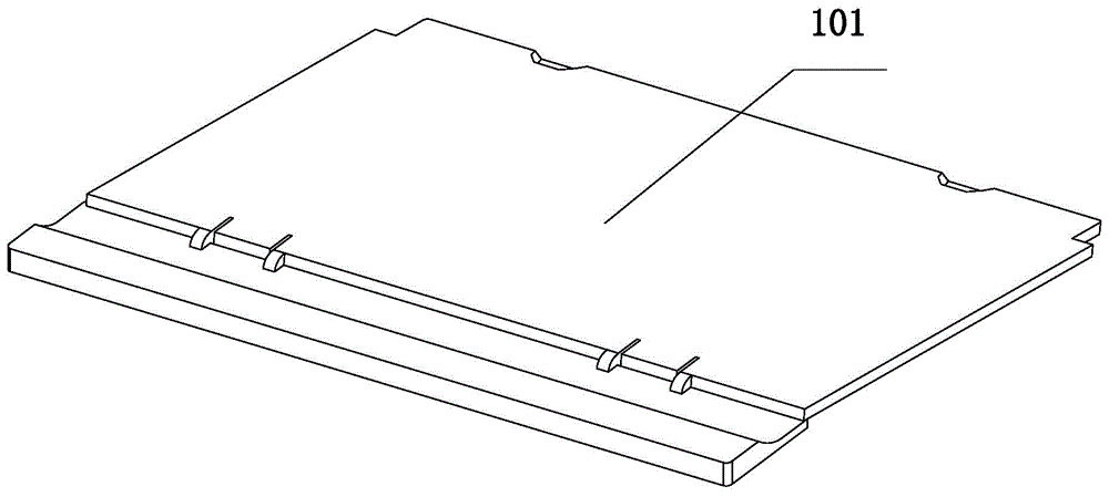
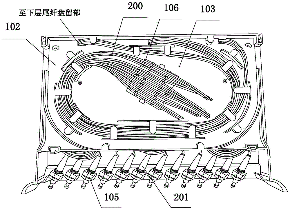
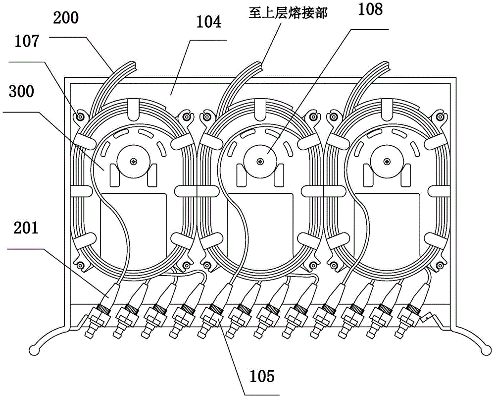
[0042] Embodiment 1, with reference to Figure 1 to Figure 8 , an integrated unit tray for optical fiber fusion, including a cover plate 101 and a unit tray body 102, the unit tray body 102 includes an upper layer of welding portion 103 and a lower layer of pigtail tray remaining portion 104, the cover plate 101 of the present invention and the unit tray body 102 The existing optical fiber fusion integrated unit tray is the same, including the first plate body connected to the unit tray body 102, and the second plate body hinged with the first plate body, the second plate body and the tail fiber tray remaining part 104 The positions of the fiber outlets correspond to each other. The first board is hinged or clipped to the unit tray body 102 , which is easy to open. When connecting the pigtail 200 , it is only necessary to turn the second board upward relative to the first board.

[0043] The fusion splicing part 103 is also the same as the existing optical fiber fusion integra...


PUM


Abstract

The invention provides an optical fiber fusion and distribution integrated unit disc, and belongs to an optical fiber fusion and distribution part. The optical fiber fusion and distribution integrated unit disc comprises a cover plate and a unit disc body. The unit disc body comprises a fusion part in the upper layer and a tail fiber coiling part in the lower layer. A plurality of fiber winding-unwinding structures used for coiling tail fibers are arranged in the tail fiber coiling part, each fiber winding-unwinding structure is formed by detachably connecting a plurality of fiber winding-unwinding discs, and the fiber winding-unwinding discs of each fiber winding-unwinding structure are stacked in the vertical direction. The optical fiber fusion and distribution integrated unit disc can be used as a distribution unit disc in an optical cable splice box, and in the optical cable splice box, the tail fibers can be directly connected with an adapter of a standard main unit disc through the tail fibers. Attenuation in the whole light path process is effectively reduced, the network quality is improved, and obstacle points caused by connecting the optical fibers with the adapter are reduced. In addition, the tail fibers in the optical fiber splice box can be orderly and tidily arranged, and disordering of the tail fibers can be avoided.

Description

technical field [0001] The invention relates to the field of optical fiber fusion, in particular to an integrated optical fiber fusion unit tray. Background technique [0002] The integrated unit panel for optical fiber fusion splicing and distribution is an important equipment for optical fiber line distribution. It is generally installed in the optical cable transfer box and can be used as a backbone unit panel or a distribution unit panel. The existing optical fiber fusion integrated unit tray includes a cover plate and a unit tray body, and the cover plate and the unit tray body are clamped or hinged. The unit tray body includes the upper layer of the fusion splicing part and the lower layer of the pigtail tray. The fusion splicing part is used for welding and reserving the optical fiber, and the pigtail tray is used for pigtail wiring. The existing pigtail tray is generally equipped with Winding fiber board or winding column, the pigtail is wound on it and then ends at...

Claims


Application Information

Patent Timeline
Patent Type & Authority Applications(China)
IPC IPC(8): G02B6/44G02B6/255
CPCG02B6/4457G02B6/255G02B6/444
Inventor 高文亭李南仁任小武
Owner 高文亭
Why Eureka
Try Eureka