Liquid crystal module full-lamination structure

A liquid crystal module and full lamination technology, applied in light guides, optics, instruments, etc., can solve problems such as waste of light sources, achieve clear image quality, increase light utilization, and increase light incidence.

Inactive Publication Date: 2015-03-25
TCL CHINA STAR OPTOELECTRONICS TECH CO LTD
View PDF6 Cites 1 Cited by
  • Summary
  • Abstract
  • Description
  • Claims
  • Application Information

AI Technical Summary

Problems solved by technology

During the light propagation process, since the optical film is an optically dense medium and the air is an optically sparse medium, when the light enters the air layer from the optical film, the refraction angle of the light is greater than the incident angle of the light, causing a lot of incident light to be reflected back to the air layer. In the backlight module, it causes waste of light source

Method used


Image

  • Liquid crystal module full-lamination structure

Examples


Embodiment Construction

[0018] In order to better illustrate the technical features and structure of the present invention, the following detailed description is given in conjunction with the preferred embodiments of the present invention and the accompanying drawings.

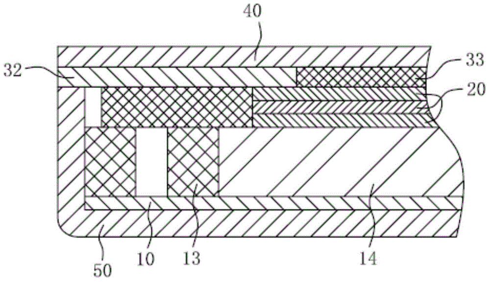
[0019] see figure 1 , a liquid crystal module fully bonded structure, including at least a housing 50, a liquid crystal panel 40, a light guide plate 14, a number of optical films 20, a reflector 10 and a light source 13, a light guide plate 14, a number of optical films 20, reflection The sheet 10 and the light source 13 are located inside the casing 50, wherein the reflective sheet 10 is located below the light guide plate 14 and is in contact with the casing 50, the light source 13 is located on the side of the light guide plate 14, and a plurality of optical films 20 are superimposed on each other. above the light guide plate 14 . The liquid crystal panel 40 is overlapped on the casing 50 . The liquid crystal panel 40 is provide...


PUM

PropertyMeasurementUnit
transmittivityaaaaaaaaaa

Abstract

A liquid crystal module full-lamination structure at least comprises a shell, a liquid crystal panel, a light guiding plate and a plurality of optical diaphragms, wherein the light guiding plate and the optical diaphragms are positioned in the shell; the optical diaphragms are stacked together and are arranged above the light guiding plate; the liquid crystal panel is in lap joint to the shell; and a buffering layer and an optical transparent adhesive tape are arranged between the liquid crystal panel and the top optical diaphragm. The optical transparent adhesive tape is arranged between the liquid crystal panel and the top optical diaphragm of the liquid crystal module full-lamination structure, a refraction angle of light emitted to the liquid crystal panel is reduced, the buffering layer surrounds the optical transparent adhesive tape, gapless sealing between the liquid crystal panel and the shell is realized, the light is stopped from leaking outwards, so that light loss is reduced effectively, the incident rate of the light emitted to the liquid crystal panel is improved, the light utilization rate is improved, and the imaging quality of the liquid crystal panel is high.

Description

technical field [0001] The invention relates to the field of manufacturing and assembling of liquid crystal modules, in particular to a full-fit structure of liquid crystal modules. Background technique [0002] In modern life, all kinds of electronic devices have entered more and more families, such as LCD TVs, LCD computers, tablet computers and touch-screen mobile phones, especially people are more and more inseparable from small electronic devices in daily life. products such as smart touchscreen phones and tablets. In the design of small electronic products, the fixed liquid crystal panel is usually fixed with black double-sided tape at the edge of the backlight source, and a black double-sided tape and a gap layer are arranged between the liquid crystal panel and the optical film, and there is air in the gap layer. In this type of bonding structure, the optical film spreads light, so that the light enters the gap layer, the light propagates through the air, and then e...

Claims


Application Information

Patent Timeline
Patent Type & Authority Applications(China)
IPC IPC(8): G02F1/1333G02F1/13357
CPCG02F1/133308G02B6/0088G02B6/0093G02F1/133615G02F2202/28G02B6/005G02B6/0055G02F1/0105G02F1/1333G02F1/133317
Inventor 张彦学
Owner TCL CHINA STAR OPTOELECTRONICS TECH CO LTD
Why Eureka
Try Eureka