
CAN signal analyzing method and device

A signal and local area technology, applied in the field of control, can solve the problems of insufficient intuitive data, low analysis efficiency, and long time consumption

Active Publication Date: 2015-03-25
SHENGRUI TRANSMISSION
View PDF2 Cites 8 Cited by
  • Summary
  • Abstract
  • Description
  • Claims
  • Application Information

AI Technical Summary

Problems solved by technology

[0004] However, in the current technology, the traced CAN signal data is directly analyzed by the CAN analysis engineer in a hexadecimal number sequence. Because the data is not intuitive enough, the CAN analysis engineer needs to complete the above-mentioned multiple items during the analysis process. Work, it takes a long time, and the efficiency of analysis is relatively low

Method used


Image

  • CAN signal analyzing method and device
  • CAN signal analyzing method and device
  • CAN signal analyzing method and device

Examples


Embodiment 1

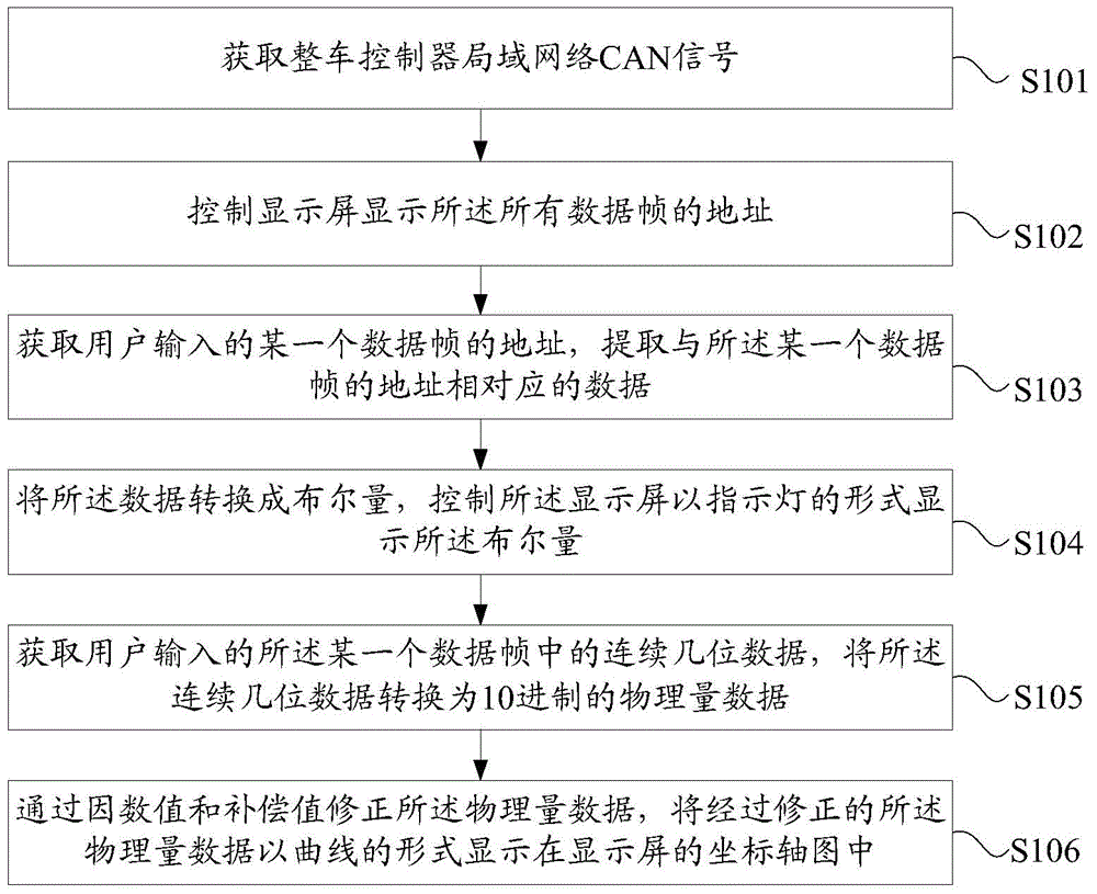
[0050] see figure 1 , figure 1 It is a flowchart of a CAN (Controller Area Network, Controller Area Network) signal analysis method provided by an embodiment of the present invention. Such as figure 1 As shown, the method includes:

[0051] Step S101, acquiring the CAN signal of the vehicle controller area network;

[0052] Specifically, the vehicle controller area network CAN signal is obtained through a USB (Universal Serial Bus, universal serial bus)-controller area network CAN adapter. The controller area network CAN signal includes addresses of all data frames.

[0053] Step S102, controlling the display screen to display the addresses of all the data frames;

[0054] Specifically, the display screen is controlled to display addresses of all data frames in a first preset area.

[0055] Step S103, obtaining the address of a certain data frame input by the user, and extracting data corresponding to the address of the certain data frame;

[0056] Specifically, the add...

Embodiment 2

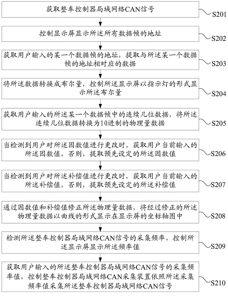
[0066] see figure 2 , figure 2 It is a flow chart of another CAN signal analysis method provided by the embodiment of the present invention. Such as figure 2 As shown, the method includes:

[0067] Step S201, acquiring the vehicle controller area network CAN signal; the controller area network CAN signal includes addresses of all data frames;

[0068] Step S202, controlling the display screen to display the addresses of all the data frames;

[0069] Step S203, obtaining the address of a certain data frame input by the user, and extracting data corresponding to the address of the certain data frame;

[0070] Step S204, converting the data into a Boolean quantity, and controlling the display screen to display the Boolean quantity in the form of an indicator light; the number of the indicator lights is 64, corresponding to 64 bits of a data frame;

[0071] Step S205, obtaining several consecutive bits of data in the certain data frame input by the user, and converting the...


PUM


Abstract

The invention discloses a CAN signal analyzing method and device. The method comprises the steps that a CAN signal of a finished car is obtained; the CAN signal comprises addresses of all data frames; a display screen is controlled to display the addresses of all the data frames; the address of one data frame input by a user is obtained, and data corresponding to the address of the input data frame are extracted; the data are converted into the Boolean quantity, and the display screen is controlled to display the Boolean quantity in the form of an indicator lamp; continuous bits of data of the data frame input by the user are obtained, and the continuous bits of data are converted into decimalism physical quantity data; the physical quantity data are corrected through the factor value and the compensation value, and the corrected physical quantity data are displayed in a coordinate axis graph of the display screen in a curve form. By means of the technical scheme, the time for a CAN analysis engineer to analyze the CAN signal of the finished car can be shortened, and the analyzing efficiency is improved.

Description

technical field [0001] The invention relates to the technical field of control, in particular to a CAN (Controller Area Network, Controller Area Network) signal analysis method and device. Background technique [0002] CAN (Controller Area Network, Controller Area Network) is one of the most widely used field buses. It serves as a micro-control communication in the automotive environment, exchanging information between the various ECUs (Electric Control Unit, Electronic Control Unit) in the vehicle, forming In the automotive electronic control network, CAN has almost become the most commonly used technical means in the field of automotive design. [0003] The analysis of the CAN signal of the whole vehicle is a necessary process to detect whether the components of the whole vehicle are working normally. In the current technology, for different vehicle CAN signals of different models, after connecting the CAN reading device, it is necessary to manually check the CAN tracking...

Claims


Application Information

Patent Timeline
IPC IPC(8): G05B19/042
CPCG05B19/042
Inventor 鲁曦郭伟李强辛彩云范维栋
Owner SHENGRUI TRANSMISSION
Learn More