Particle diffraction diagram simulating method through geometrical optics ray tracing

A technology of ray tracing and diffraction diagrams, which is applied in design optimization/simulation, symbol schematic diagrams, image data processing, etc., and can solve problems such as increased computing costs

Active Publication Date: 2015-03-25
TIANJIN UNIV
View PDF3 Cites 3 Cited by
  • Summary
  • Abstract
  • Description
  • Claims
  • Application Information

AI Technical Summary

Problems solved by technology

[0004] However, DIFC technology usually uses a microscopic optical system to obtain particle diffraction images. If methods such as FDTD or DDA are directly used to calculate the diffraction light field containing microscopic optical elements, it will bring great challenges to system modeling. It is foreseeable that the calculation greatly increased cost

Method used


Image

  • Particle diffraction diagram simulating method through geometrical optics ray tracing
  • Particle diffraction diagram simulating method through geometrical optics ray tracing
  • Particle diffraction diagram simulating method through geometrical optics ray tracing

Examples


Embodiment Construction

[0042] The method for simulating particle diffraction patterns by geometrical optics ray tracing of the present invention will be described in detail below in conjunction with the embodiments and accompanying drawings.

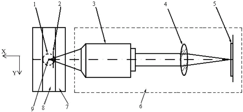
[0043] The method for simulating particle diffraction patterns by geometrical optics ray tracing of the present invention operates on a microscopic imaging system of a diffraction imaging flow cytometer. The diffraction imaging flow cytometer microscopic imaging system is as figure 1 As shown, it includes: fluid (water) 8 placed in the fluid chamber (glass material) 7, particles (cells) 9 placed in the fluid (water) 8 in the fluid chamber 7, and the outside of the fluid chamber 7 corresponds to the The particles 9 are provided with a diffraction imaging flow cytometry microscopic imaging system 6, and the diffraction imaging flow cytometry microscopic imaging system 6 is composed of an infinity microscopic objective lens 3, a cylinder lens 4 and a CCD sensor a...


PUM


Abstract

Disclosed is a particle diffraction diagram simulating method through geometrical optics ray tracing. The method comprises the steps that (1) light of a light source is generated through a far scattered light field, specifically, the far scattered light field is obtained, a matrix element S11 is projected to a microscope system incident plane x=x0, a light intensity distribution diagram of the scattered light field is obtained, a ray tracing light source is formed, and rays are built for all points (y, z) for imaging through a diffraction imaging flow cytometry microimaging system; (2) tracing calculation is carried out on each generated ray according to the Fresnel diffraction law; (3) after tracing calculation of all the rays is completed, cross points of the rays and an imaging plane are obtained, and the distribution density diagram of the cross points is the simulated diffraction diagram. The particle far scattered field is processed into the light source needed by geometrical optics, micrographic optical system diffraction imaging is calculated through ray tracing, a coherent diffraction optical field of the micrographic optical system of a complex structure can be prevented from being calculated, diffraction diagram calculation on various complex micrographic optical systems can be achieved, and graphical display interfaces are very convenient to operate.

Description

technical field [0001] The invention relates to a simulation method for particle diffraction imaging. In particular, it relates to a method for simulating particle diffraction diagrams by geometrical optics ray tracing for micron-scale particles under the condition of coherent light illumination to acquire diffraction images by ray tracing on a microscopic imaging system. Background technique [0002] X-ray diffraction measurement is a common method to determine the microstructure of substances. Similarly, photoelectromagnetic waves in the ultraviolet, visible and infrared bands can also be used to measure micron-scale particles such as cell structures. The size of a single cell is exactly on the order of microns, which is within the range of electromagnetic wave diffraction measurements in these bands. Therefore, there is a method of exciting with coherent light, measuring coherent scattered light with diffraction imaging method, and finally determining the cell structure....

Claims


Application Information

Patent Timeline
Patent Type & Authority Applications(China)
IPC IPC(8): G06T17/00G06F17/50
CPCG06F30/20G06F2111/12
Inventor 撒昱冯远明胡新华
Owner TIANJIN UNIV
Why Eureka
Try Eureka