Linear variable differential transformer and winding method thereof

A differential sensor and variable technology, applied in the field of displacement sensors, can solve the problems of unoptimized electrical performance and poor symmetry, and achieve the effect of compact structure, compact winding and improved consistency

Active Publication Date: 2015-03-25
MEASUREMENT SPECIALTIES CHINA
View PDF10 Cites 17 Cited by
  • Summary
  • Abstract
  • Description
  • Claims
  • Application Information

AI Technical Summary

Problems solved by technology

[0006] The purpose of the embodiments of the present invention is to provide a linear variable differential transformer, aiming to solve th...

Method used


Image

  • Linear variable differential transformer and winding method thereof
  • Linear variable differential transformer and winding method thereof
  • Linear variable differential transformer and winding method thereof

Examples


Embodiment 1

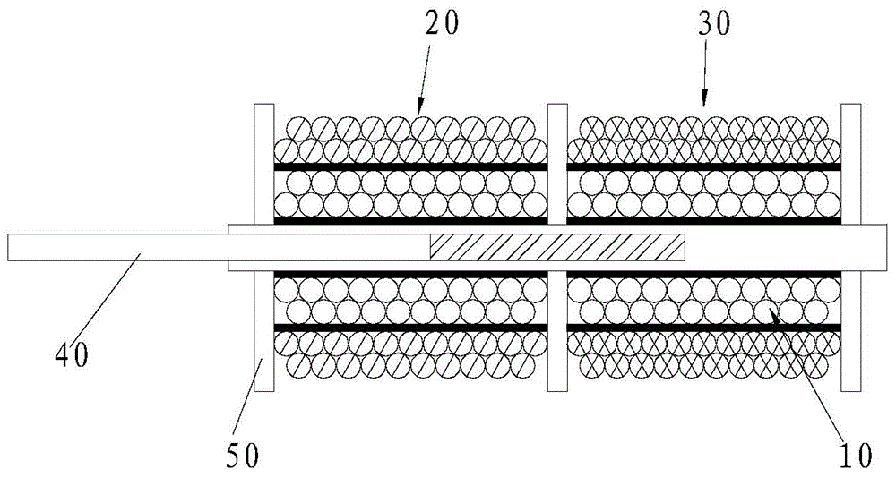
[0052] See Figure 8 , in this embodiment, the beginning of the first flat winding layer 21 is at the center of the primary winding 1, and the enameled wire is wound flat on the primary winding 1 for one or more layers to form the first flat winding layer 21, the first flat winding layer The length of 21 is half of the length of the primary winding 1, and the structure of each wound coil is compact, and the coil density of the winding wire is the same. The wire mode is wound at the center of the first flat winding layer 21, and the length of the inter-winding is half of the first flat winding layer 21, and the other half adopts the flat winding method, and is wound to the end of the first flat winding layer 21, and then Winding to the center of the first flat winding layer 21, the coil density of the first intermediate winding layer 22 thus formed gradually changes, and the starting end of the second flat winding layer 31 is also at the center of the primary winding 1, and the...

Embodiment 2

[0056] See Figure 11 , as another preferred embodiment, the technology not introduced in this embodiment can be the same as the relevant content in the previous embodiment, the enameled wire is wound into the first flat winding layer 21a from the end of the primary winding 1a, and the first flat winding layer 21a The length is half of the length of the primary winding 1a, and the enameled wire is wound from the end of the first flat winding layer 21a in the opposite direction to the beginning of the first flat winding layer to form the first intermediate winding layer 22a, and the end of the first intermediate winding layer 22a Pull it out for wiring in the next step. The enameled wire is wound from the end of the primary winding 1a to the remaining half, and wound into the second flat winding layer 31a. The winding direction of the second flat winding layer 31a and the first flat winding layer 21a On the contrary, the enameled wire is wound around the second winding layer 32...


PUM


Abstract

The invention belongs to the technical field of displacement sensors and provides a linear variable differential transformer. Magnetic flux generated by coupling of a first secondary winding and a primary winding and magnetic flux generated by coupling of a second secondary winding and the primary winding are symmetric, so that symmetry of the linear variable differential transformer is improved. Coils are compact in structures, improving anti-vibration, anti-mechanical shock and anti-heat shock capabilities of the linear variable differential transformer, and the user requirements for high precision, good temperature characteristic and high reliability and stability in the linear variable differential transformer in the aviation field are met. The invention further provides a winding method of the linear variable differential transformer. The winding method is simple to operate, turn numbers per unit length of the coils in the first secondary winding and the second secondary winding linearly progressively increase or decrease, the secondary windings output induced electromotive force linearly progressively increases or decreases with core displacement, zero residual voltage is reduced, and electrical performance and temperature stability of the linear variable differential transformer are enhanced.

Description

technical field [0001] The invention belongs to the technical field of displacement sensors, and in particular relates to a linear variable differential transformer and a winding method thereof. Background technique [0002] Linear variable differential transformers such as figure 1 As shown, it includes a primary winding 10, a first secondary winding 20 and a second secondary winding 30, an iron core 40 and a skeleton 50, and the enameled wire is wound on the skeleton to form the primary winding 10, the first secondary winding 20 and the The second secondary winding 30, wherein the output voltages of the first secondary winding 20 and the second secondary winding 30 are reversely connected in series, the primary winding 10 and the first secondary winding 20, the second secondary winding 30 between The coupling changes with the movement of the iron core 40, that is, the mutual inductance between the windings changes with the measured displacement, wherein the number of turn...

Claims


Application Information

Patent Timeline
IPC IPC(8): H01F27/30H01F27/32H01F41/06G01B7/02H01F41/066H01F41/069
CPCG01B7/02H01F27/306H01F27/323H01F41/064
Inventor 石德皓张金健钟金云
Owner MEASUREMENT SPECIALTIES CHINA
Why Eureka
Try Eureka