
Low-temperature cooling system of superconduction high-intensity magnetic field magnetron sputtering cathode

A technology of magnetron sputtering and cooling system, which is applied to discharge tubes, electrical components, circuits, etc., can solve the problems of reducing the service life of refrigerators, increasing operating costs, difficult to meet the rapidity of cooling and temperature recovery, and achieving rapid cooling and the effect of rewarming

Inactive Publication Date: 2015-03-25
INST OF ELECTRICAL ENG CHINESE ACAD OF SCI
View PDF7 Cites 6 Cited by
  • Summary
  • Abstract
  • Description
  • Claims
  • Application Information

AI Technical Summary

Problems solved by technology

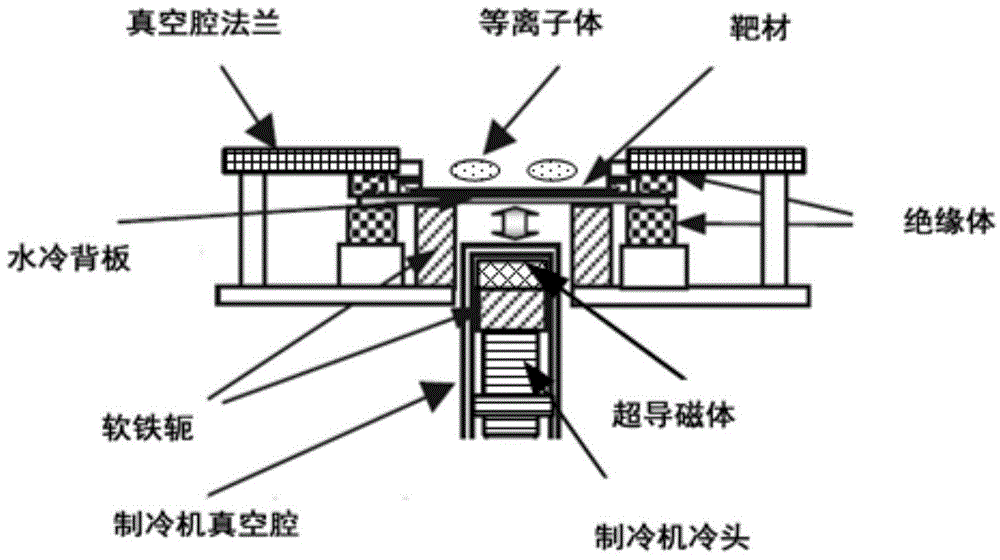
Since the substrate and target materials need to be replaced intermittently in the magnetron sputtering coating process, which belongs to the intermittent operation condition, it needs regular or irregular rapid (minute level) cooling and temperature recovery. It is difficult to meet the cooling and temperature recovery requirements by using conduction cooling. Rapidity, which will greatly reduce the efficiency of the coating process
In addition, because the refrigerator needs to be started and stopped frequently, it not only increases the operating cost, but also reduces the service life of the refrigerator

Method used


Image

  • Low-temperature cooling system of superconduction high-intensity magnetic field magnetron sputtering cathode
  • Low-temperature cooling system of superconduction high-intensity magnetic field magnetron sputtering cathode
  • Low-temperature cooling system of superconduction high-intensity magnetic field magnetron sputtering cathode

Examples


Embodiment Construction

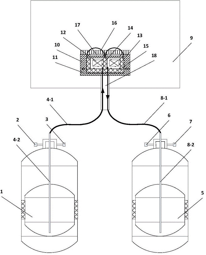
[0017] figure 2 Shown is the specific embodiment 1 of the low temperature cooling system for the superconducting strong magnetic field magnetron sputtering cathode of the present invention. Such as figure 2 As shown, the cryogenic cooling system of the present invention consists of a first liquid nitrogen storage Dewar 1, a first booster valve 2, a first deflation valve 3, a first infusion pipeline 4-1, a first infusion rod 4-2, a second Liquid nitrogen storage Dewar 5, second booster valve 6, second deflation valve 7, second infusion pipeline 8-1, second infusion rod 8-2, vacuum cavity 9, magnet Dewar upper cover 10, and The magnet Dewar base 11 is composed. The first booster valve 2 and the first purge valve 3 are installed on the first liquid nitrogen storage Dewar 1 for controlling the nitrogen pressure inside the first liquid nitrogen storage Dewar 1, and the first infusion pipeline 4-1 passes through the first liquid nitrogen storage Dewar 1 An infusion rod 4-2 is i...


PUM


Abstract

The invention relates to a low-temperature cooling system of a superconduction high-intensity magnetic field magnetron sputtering cathode. The low-temperature cooling system is composed of two liquid nitrogen storage Dewars (1 and 5), pressure increasing valves (2 and 6), deflation valves (3 and 7), a first liquid transmitting pipe (4-1), a first liquid transmitting rod (4-2), a second liquid transmitting pipe (8-1), a second liquid transmitting rod (8-2), a vacuum cavity (9), a magnetic body Dewar upper cover (10) and a magnetic body Dewar base (11). A superconducting magnetic body (12), an outer magnetic yoke (13), an inner magnetic yoke (14) and a bottom magnetic yoke (15) are installed in closed space defined by the magnetic body Dewar upper cover (10) and the magnetic body Dewar base (11), the magnetic body Dewar upper cover (10) and a cathode target material (16) are fixed together, and part of a vacuum gap (17) is reserved between the magnetic body Dewar upper cover (10) and the cathode target material (16). Forced flowed cooling is carried out on the superconducting magnetic body (12) through liquid nitrogen; the two liquid nitrogen storage Dewars (1 and 5) alternatively work to cool the superconducting magnetic body (12) and the cathode target material (16).

Description

technical field [0001] The invention relates to a low-temperature cooling system for a superconducting strong magnetic field magnetron sputtering cathode. Background technique [0002] In order to obtain high-quality films, high deposition rates, and high target utilization, various magnetron sputtering devices have been developed. The strong magnetic field magnetron sputtering device can discharge at a lower air pressure. The combination of high magnetic field and low air pressure can suppress the high-energy bombardment of high-energy ions on the deposited film, reduce the scattering of particles, and obtain high-quality films. However, since the magnetic field of the permanent magnet high magnetic field magnetron sputtering device cannot be made very strong, there are very few researches and applications on the high magnetic field magnetron sputtering device at present. In 2003, Mizutani of Nagoya University in Japan first developed a high-magnetic field circular magnetr...

Claims


Application Information

Patent Timeline
IPC IPC(8): H01J37/07H01J37/34
CPCH01J37/32532H01J37/3405
Inventor 邱清泉屈飞宋乃浩张志丰古宏伟张国民戴少涛肖立业
Owner INST OF ELECTRICAL ENG CHINESE ACAD OF SCI
Learn More