

Spin treatment apparatus
A technology for processing devices and rotating bodies, which is applied to devices, optics, instruments, etc. that apply liquid to the surface, can solve the problems of deviation of the position of the substrate from the predetermined position, uneven rotation of the clamping pin, etc., so as to suppress the deviation of the position of the substrate. Effect
- Summary
- Abstract
- Description
- Claims
- Application Information
AI Technical Summary
Problems solved by technology
Method used
Image

Examples
no. 1 Embodiment approach
[0021] refer to Figure 1 to Figure 8 The first embodiment will be described.
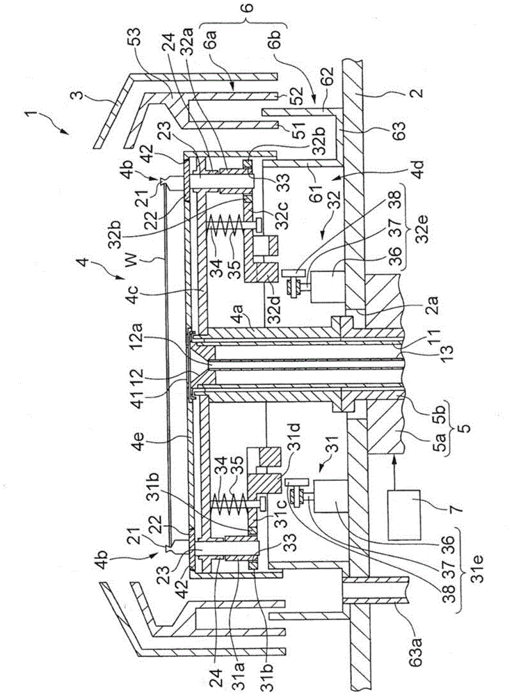
[0022] Such as figure 1 As shown, the spin processing device 1 according to the first embodiment includes a base body 2 serving as a base, a cup body 3 with an open upper surface, a rotating body 4 rotating inside the cup body 3 , and a device for rotating the rotating body 4 . A drive motor 5, an annular liquid receiving unit 6 surrounding the rotating body 4, and a control unit (for example, a microcomputer, etc.) 7 for controlling each unit.
[0023] The base body 2 is formed in a plate shape, and a through-hole 2 a is formed at the center of the bottom surface of the base body 2 . In addition, a plurality of discharge pipes (not shown) for discharging waste liquid are connected at predetermined intervals to the peripheral portion of the base body 2 .
[0024] The cup body 3 is formed in a cylindrical shape (annular shape) with an open upper surface and a lower surface, and accommodates the r...
no. 2 Embodiment approach
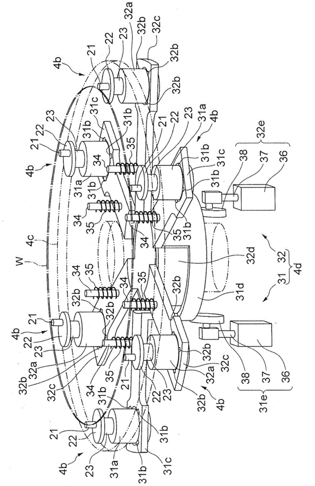
[0072] refer to Figure 9 and Figure 10 The second embodiment will be described.
[0073] The second embodiment is basically the same as the first embodiment. Therefore, in the second embodiment, differences from the first embodiment (the structure of the rotating magnet 31 b ) will be described, and the same parts as those described in the first embodiment will be denoted by the same reference numerals, and description thereof will be omitted.
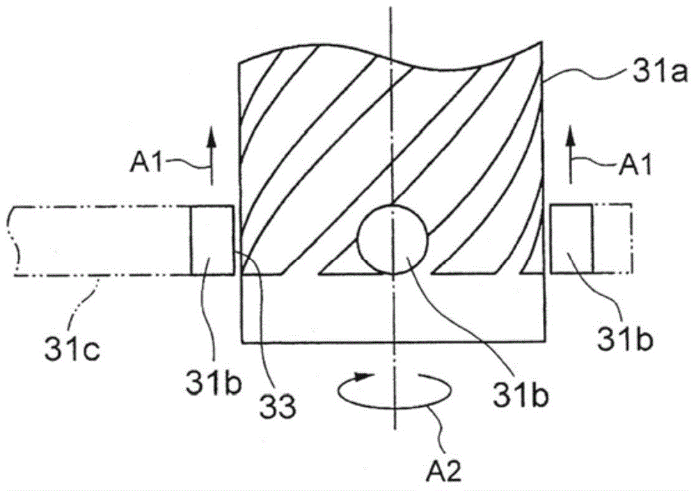
[0074] Such as Figure 9 As shown, in the spin processing device 1 according to the second embodiment, the rotation magnets 31b are provided at the front ends of the upper and lower arms 31c, and the rotation magnets 32b are respectively provided at the front ends of the upper and lower arms 32c. Since these rotation magnets 31b and 32b have the same structure, description of the rotation magnet 32b will be omitted. In addition, each of the upper and lower arms 31c and 32c does not have the through-hole 33 of the first embodiment...
no. 3 Embodiment approach
[0081] refer to Figure 11 The third embodiment will be described.
[0082] The third embodiment is basically the same as the first embodiment. Therefore, in the third embodiment, the difference from the first embodiment (the arm moving mechanism) will be described, and the same parts as those described in the first embodiment will be assigned the same reference numerals, and their description will be omitted.
[0083] Such as Figure 11 As shown, the spin processing device 1 of the third embodiment is configured so that the upper and lower arms (moving the upper and lower arms 101) of one or two clamping pins (clamping pins) 21 of the upper and lower arms 31c or 32c and the other A mechanism that moves the upper and lower arms independently up and down in parallel (arm movement mechanism). The movable upper and lower arms 101 are pressed by a spring 103 so as to be independently movable in parallel along the sliding shaft 102 fixed to the upper and lower rings 32d. Furthe...
PUM
 Abstract
Description
Claims
Application Information