Method for manufacturing semi-floating gate device with planar channels

A semi-floating gate device and planar channel technology, which is applied in semiconductor/solid-state device manufacturing, semiconductor devices, electrical components, etc., can solve the problems of metal gate damage and poor high temperature resistance of metal gate, so as to avoid damage, process The process is simple and the effect of improving performance

Active Publication Date: 2015-03-25
SUZHOU ORIENTAL SEMICONDUCTOR CO LTD
3 Cites 16 Cited by

AI-Extracted Technical Summary

Problems solved by technology

However, the high temperature resistance of the metal gate is poor, and high-temperature annealing is required after the formati...

Abstract

The invention belongs to the technical field of manufacturing of semiconductor devices and particularly relates to a method for manufacturing a semi-floating gate device with planar channels. The method for manufacturing the semi-floating gate device with the planar channels comprises the steps that the semi-floating gate device with the planar channels is manufactured through a post-gate technology; after a source contact area and a drain contact area are formed, a polycrystalline silicone control gate sacrificial material is removed through etching firstly, secondly a metal control gate material occupies the position originally occupied by the polycrystalline silicone control gate sacrificial material, and then a metal control gate is formed. The metal control gate can be prevented from being damaged in a high-temperature annealing process of a source contact area and a drain contact area, and the performance of the semi-floating gate device with the planar channels is improved. In addition, according to the method, self-alignment technology is adopted to manufacture the source contact area and the drain contact area of the semi-floating gate device, the technology process is simple and stable, and production cost is reduced.

Application Domain

Technology Topic

Planar channelControl grid +8

Image

  • Method for manufacturing semi-floating gate device with planar channels
  • Method for manufacturing semi-floating gate device with planar channels
  • Method for manufacturing semi-floating gate device with planar channels

Examples

  • Experimental program(1)

Example Embodiment

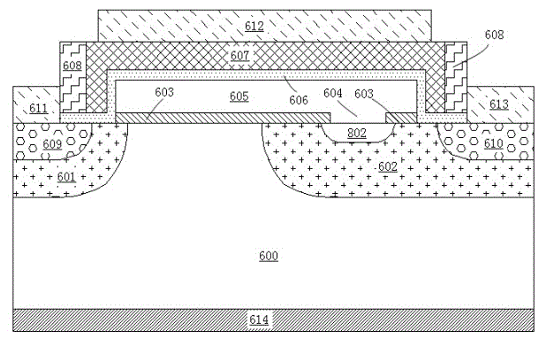
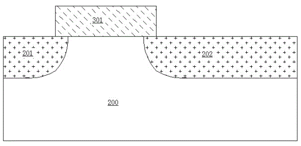
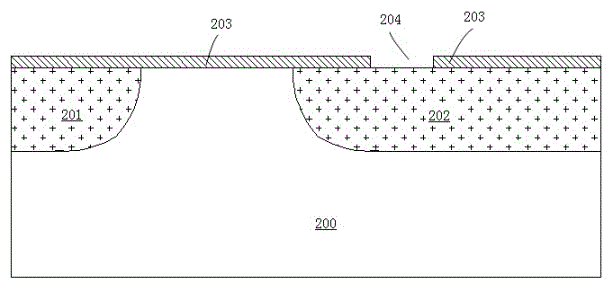
[0038] The present invention will be further described in detail below with reference to the drawings and specific embodiments. In the figure, for the convenience of description, the thickness of the layers and regions are enlarged, and the size shown does not represent the actual size. The reference figure is a schematic diagram of an idealized embodiment of the present invention. The embodiment shown in the present invention should not be regarded as limited to the specific shape of the area shown in the figure, but includes the resulting shape, such as deviations caused by manufacturing. For example, the curves obtained by etching usually have the characteristics of bending or roundness, but in the embodiment of the present invention, they are all represented by rectangles. The representation in the figure is schematic, but this should not be considered as limiting the scope of the present invention. At the same time, in the following description, the term substrate used can be understood to include the semiconductor substrate being processed, and may include other thin film layers prepared thereon.
[0039] The following description is a process flow of an embodiment of manufacturing a planar channel half-floating gate device using a method of manufacturing a planar channel half-floating gate device of the present invention.
[0040] First, like figure 2 As shown, a layer of photoresist 301 is deposited on the surface of a semiconductor substrate 200 with a first doping type in which a shallow trench isolation structure (not shown in the figure) has been formed, masked, exposed, and developed to form a pattern Then, a source region 201 and a drain region 202 with the second doping type are formed in the semiconductor substrate 200 on both sides of the formed photoresist pattern through an ion implantation process, and are located in the source region 201 and the drain region 202 The semiconductor substrate with the first doping type in between forms the channel region of the device. The semiconductor substrate 200 may be monocrystalline silicon, polycrystalline silicon, or silicon on insulator. The first doping type is p-type, and the second doping type is n-type; or, correspondingly, the first doping type is n-type, and the second doping type is p-type.
[0041] After the photoresist 301 is stripped off, a first insulating film 203 is grown on the surface of the semiconductor substrate 200. The first insulating film 203 can be silicon dioxide, silicon nitride, silicon oxynitride, or high-dielectric constant. Insulating materials or laminates between them. Next, a layer of photoresist is deposited on the first insulating film 203 and the position of the floating gate opening area 204 is defined by a photolithography process, and then the exposed first layer of insulation is etched away using the photoresist as a mask The thin film 203 forms the floating gate opening area 204, and the photoresist is removed as image 3 Shown. The floating gate opening region 204 is located above the drain region 202, and the distance between its side edge close to the channel region and the channel region is greater than 1 nanometer.
[0042] Next, a layer of polysilicon with the first doping type is deposited on the exposed surface of the formed structure, and then a layer of photoresist is deposited on the formed polysilicon with the first doping type and passed through The photolithography process defines the position of the floating gate of the device, and then uses the photoresist as a mask to etch the exposed polysilicon with the first doping type, and the remaining polysilicon with the first doping type after etching The floating gate 205 of the device is formed. Then use the floating gate 205 as a mask to continue to etch away the exposed first insulating film 203. After stripping off the photoresist, Figure 4 Shown. The floating gate 205 should cover at least the channel region and the floating gate opening area 204. The doped impurities in the floating gate 205 will diffuse into the drain region 202 through the floating gate opening region 204 under the floating gate 205 to form a diffusion region 402, and the floating gate 205 and the drain region 202 will form a pn junction through the floating gate opening region 204 contact.
[0043] Next, a second insulating film 206 is deposited to cover the formed structure. The second insulating film 206 can be silicon dioxide, silicon nitride, silicon oxynitride, an insulating material with a high dielectric constant, or a combination of these. Between the stacks. Then a layer of polysilicon sacrificial material is deposited on the second insulating film 206, and a third insulating film 401 is deposited on the polysilicon sacrificial material. The third insulating film 401 is silicon dioxide or silicon nitride. Then, the third insulating film 401 and the polysilicon sacrificial material formed are etched through a photolithography process and an etching process, and the remaining polysilicon sacrificial material after etching forms a polysilicon control gate sacrificial material 207, and the polysilicon control gate sacrificial material 207 is along the trench The length in the track direction should exceed the floating gate 205, and cover and surround the floating gate 205. After stripping the photoresist, such as Figure 5a Shown. Optionally, the third insulating film 401 and the polysilicon sacrificial material are etched through a photolithography process and an etching process, and the polysilicon sacrificial material remaining after etching forms the polysilicon control gate sacrificial material 207 of the device, and the polysilicon control gate sacrificial material 207 is The length of the drain region 202 along the channel direction only exceeds the floating gate 205, such as Figure 5b Shown.
[0044] Next, a fourth insulating film is deposited to cover the formed structure, and the formed fourth insulating film is etched back to form gate spacers 208 on both sides of the polysilicon control gate sacrificial material 207, and then along Continue to etch away the exposed second insulating film 206 with the gate sidewall 208, such as Image 6 Shown. The gate spacer 208 may be silicon dioxide or silicon nitride, and the fourth insulating film may be silicon oxide or silicon nitride.
[0045] Next, source and drain etches are performed on both sides of the formed gate sidewall spacers 208, and silicon germanium or silicon carbide materials are epitaxially epitaxially processed at the positions after the source and drain etches to form source contact regions 209 and drain contacts Area 210, such as Figure 7a Shown. Optionally, source and drain etching and epitaxial processes may not be performed, and ion implantation is directly used to form high-concentration ion doped regions in the source region 201 and the drain region 202 to form the source contact region 209 and the drain contact region. Area 210, such as Figure 7b Shown.
[0046] Next, like Figure 7a As shown, a first layer of interlayer dielectric material 211 is deposited covering the formed structure, and the formed first layer of interlayer dielectric material 211 is polished by chemical mechanical polishing technology until the polysilicon control gate sacrificial material 207 is exposed, such as Figure 8 Shown. Then etch away the exposed polysilicon control gate sacrificial material 207, and continue to etch away the exposed second layer of insulating film 206, such as Picture 9 Shown. Then, a fifth insulating film 212 and a metal control gate material are deposited on the surface of the formed structure, and then chemical mechanical polishing is performed so that the polished metal control gate material occupies the position of the original polysilicon control gate sacrificial material 207 to form a metal Control grid 213, such as Picture 10 Shown. Optionally, the second insulating film 206 may not be etched away, and the fifth insulating film 212 and the metal control gate material may be deposited directly after the polysilicon control gate sacrificial material 207 is etched away, or the fifth insulating film 212 and the metal control gate material may not be etched away. The second insulating film 206 directly covers the second insulating film 206 after the polysilicon control gate sacrificial material 207 is etched away to form a metal control gate material. The fifth insulating film 212 may be silicon dioxide, silicon nitride, silicon oxynitride, an insulating material with a high dielectric constant, or a stacked layer between them.
[0047] Finally, such as Picture 11 As shown, a second layer of interlayer dielectric material 214 is deposited covering the formed structure, and then contact holes are formed in the formed second layer of interlayer dielectric material 214 and the first layer of interlayer dielectric material 211, and a source electrode is formed 215, the drain electrode 217 and the gate electrode 216, the process is well-known in the industry.
[0048] Picture 12 In order to use the method of manufacturing a planar channel half-floating gate device of the present invention, an embodiment of the planar channel half-floating gate device structure of a dual memory cell is made of two Picture 11 The half-floating gate device of the planar channel shown is constituted, and the two half-floating gate devices of the planar channel have a symmetrical structure. Such as Picture 12 As shown, the two planar channel half-floating gate devices share the drain region 202, the drain region contact region 210 and the drain electrode 217, and the planar channel half-floating gate device structure of the dual memory cell can store two bits of data.
[0049] Figure 13 In order to use the method of manufacturing a planar channel half-floating gate device of the present invention, a plurality of such as Picture 11 The illustrated schematic circuit diagram of a memory cell array composed of planar channel half-floating gate devices. Such as Figure 13 As shown, among the multiple source lines SL 603a-603b, any one of them is connected to the source of the multiple half-floating gate devices. Among the plurality of word lines WL 601a-601d, any one of them is connected to the control gate of the plurality of half-floating gate devices. Among the multiple bit lines BL 602a-602d, any one of them is connected to the drains of multiple half-floating gate devices. The combination of any one of the multiple bit lines BL 602a-602d and any one of the multiple word lines WL 601a-601d can select an independent half-floating gate device. The word lines WL 601a-601d can be selected by the word line address decoder 901, and the bit lines BL 602a-602d can be selected by a bit line selection control module 902. The bit line selection control module 902 generally includes an address decoder and a multiplexer. And a set of induction amplifiers. At the same time, the source lines SL 603a and 603b can be connected by a common source line or a source line selection control module.
[0050] As described above, without departing from the spirit and scope of the present invention, many widely different embodiments can be constructed. It should be understood that, except as defined by the appended claims, the present invention is not limited to the specific examples described in the specification.

PUM

no PUM

Description & Claims & Application Information

We can also present the details of the Description, Claims and Application information to help users get a comprehensive understanding of the technical details of the patent, such as background art, summary of invention, brief description of drawings, description of embodiments, and other original content. On the other hand, users can also determine the specific scope of protection of the technology through the list of claims; as well as understand the changes in the life cycle of the technology with the presentation of the patent timeline. Login to view more.

Similar technology patents

Method and apparatus for increasing angiogenic, growth factor in heart muscle

InactiveUS7107997B1Exposure be continuousAvoid damageDiagnosticsSurgical instrument detailsAngiogenesis FactorFactor ii
Owner:MOSES JEFFREY WARREN +3

Classification and recommendation of technical efficacy words

  • Avoid damage
  • Improve performance
Why Eureka
Try Eureka