
Semiconductor device

一种半导体、体区域的技术,应用在半导体器件、电气元件、电路等方向,能够解决终端区域温度变高等问题

Inactive Publication Date: 2015-03-25
TOYOTA JIDOSHA KK
View PDF8 Cites 7 Cited by
  • Summary
  • Abstract
  • Description
  • Claims
  • Application Information

AI Technical Summary

Problems solved by technology

Therefore, if the breakdown current flows through the terminal area, it is disadvantageous that the temperature of the terminal area tends to become high

Method used


Image

  • Semiconductor device
  • Semiconductor device
  • Semiconductor device

Examples


Embodiment Construction

[0011] Main features of embodiments of the present invention will be described below. Please note that the technical elements described below are mutually independent technical elements, and exert technical usefulness individually or in various combinations.

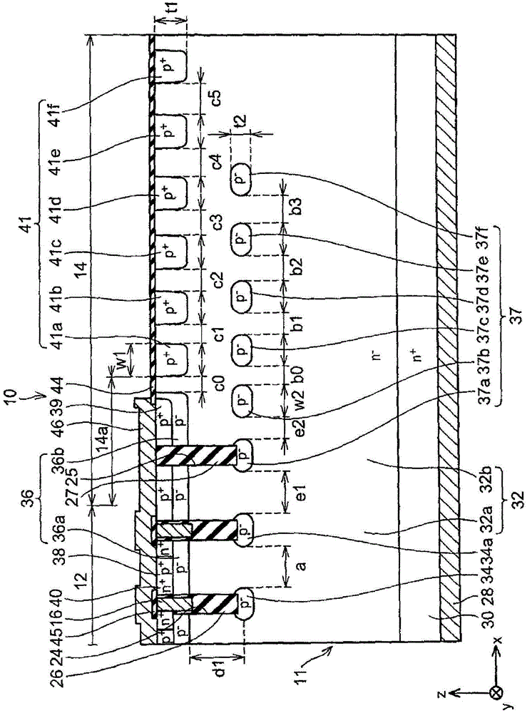
[0012] In an embodiment of the present invention, the termination region may further include a second body region. The second body region has the first conductivity type, is placed in a range toward the top surface of the semiconductor substrate and is partially arranged on the element region side, and is formed continuously from the first body region. The FLR region is arranged away from the second body region. The second drift region is in contact with the bottom and side surfaces of the second body region. The second drift region may be configured to separate the second body region from the FLR region. When viewing the semiconductor substrate in a planar manner, the second floating region may include at least one l...


PUM


Abstract

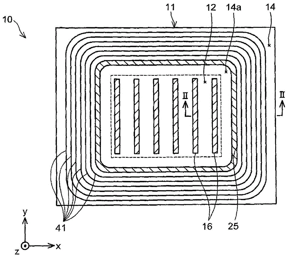
A semiconductor device includes a semiconductor substrate (11) having an element region (12) and a termination region (14). The element region includes a first body region (36a 38) having a first conductivity type, a first drift region (32) having a second conductivity type, and first floating regions (34) having the first conductivity type. The termination region includes FLR regions (41), a second drift region (32b) and second floating regions (37). The FLR regions have the first conductivity type and surrounds the element region. The second drift region has the second conductivity type, makes contact with and surrounds the FLR regions. The second floating regions have the first conductivity type and is surrounded by the second drift region. The second floating regions surround the element region. At least one of the second floating regions is placed at an element region side relative to the closest one of the FLR regions to the element region.

Description

technical field [0001] The present invention relates to a semiconductor device. Background technique [0002] Japanese Patent Application Serial No. 2008-135522 (JP 2008-135522 A) describes a semiconductor device in which an element region and a terminal region are formed in a semiconductor substrate. In the element region, a plurality of linear trench gate electrodes are formed, and in the termination region, a plurality of termination trenches disposed around the plurality of trench gate electrodes are formed. A P-type floating region is formed on the bottom surface of the termination trench. The floating region is surrounded by an n-type drift region. The semiconductor device is configured such that the distance between floating regions adjacent to each other is optimized, thereby improving the uniformity of breakdown voltage in the termination region. [0003] In recent years, it is desired to develop semiconductor devices with low loss. As one method of achieving lo...

Claims


Application Information

Patent Timeline
Patent Type & Authority Applications(China)
IPC IPC(8): H01L29/06H01L29/78
CPCH01L29/0603H01L29/4236H01L29/7811H01L29/7813H01L29/42368H01L29/0619H01L29/0623H01L29/0653H01L29/7397H01L29/7801
Inventor 斋藤顺青井佐智子渡辺行彦山本敏雅
Owner TOYOTA JIDOSHA KK
Learn More