
Super-capacitor power bank

A super capacitor and super capacitor technology, applied in battery circuit devices, current collectors, electric vehicles, etc., can solve the problems of long charging time, waste of time, waiting for a long time, etc., and achieve the effect of fast charging speed and extremely fast charging speed.

Inactive Publication Date: 2015-03-25
SHENZHEN XINGJISHENG ELECTRONICS +1
View PDF7 Cites 2 Cited by
  • Summary
  • Abstract
  • Description
  • Claims
  • Application Information

AI Technical Summary

Problems solved by technology

There is a defect that the charging time is too long, and the user has to wait for a long time to carry it out once fully charged, resulting in a waste of time and bringing a lot of inconvenience to the user

Method used


Image

  • Super-capacitor power bank
  • Super-capacitor power bank
  • Super-capacitor power bank

Examples


Embodiment Construction

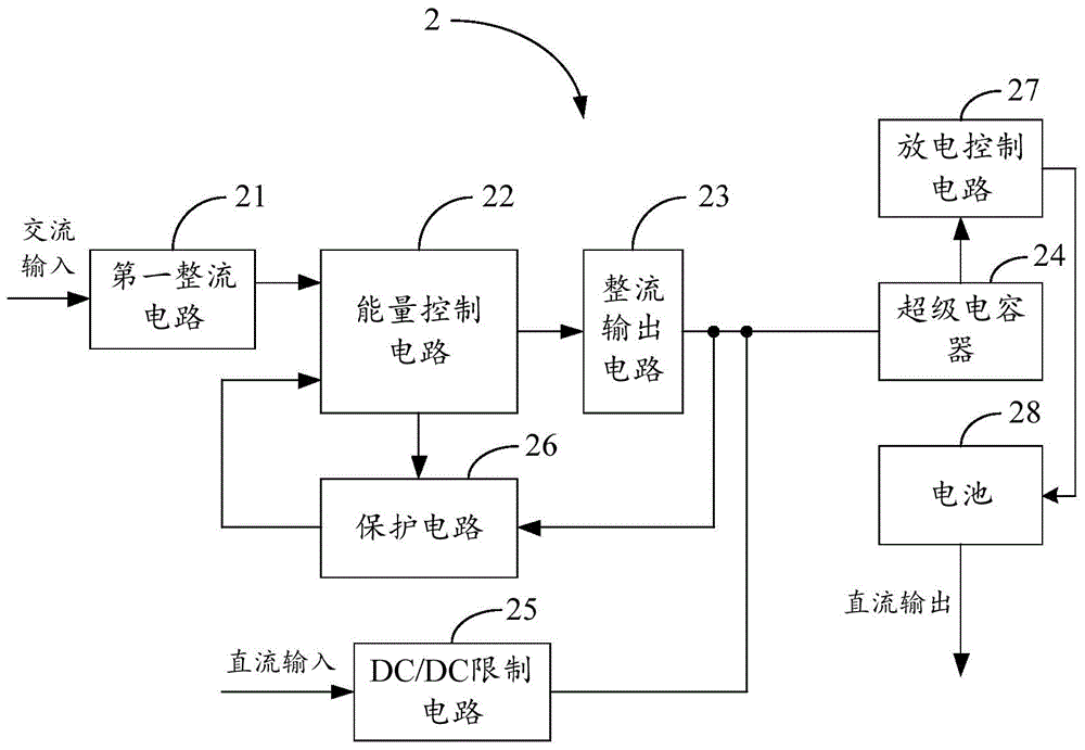
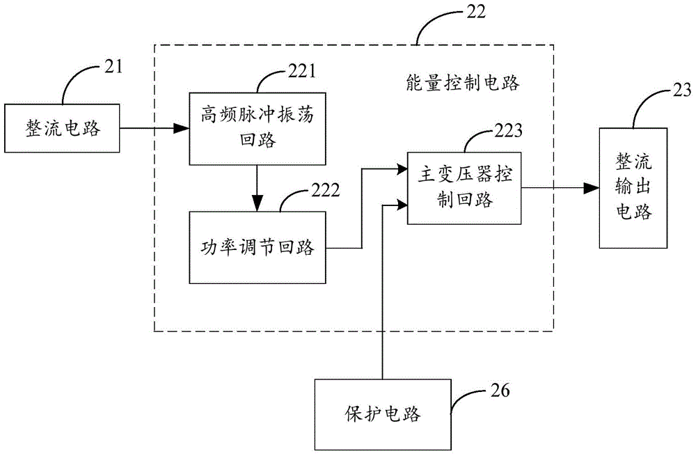
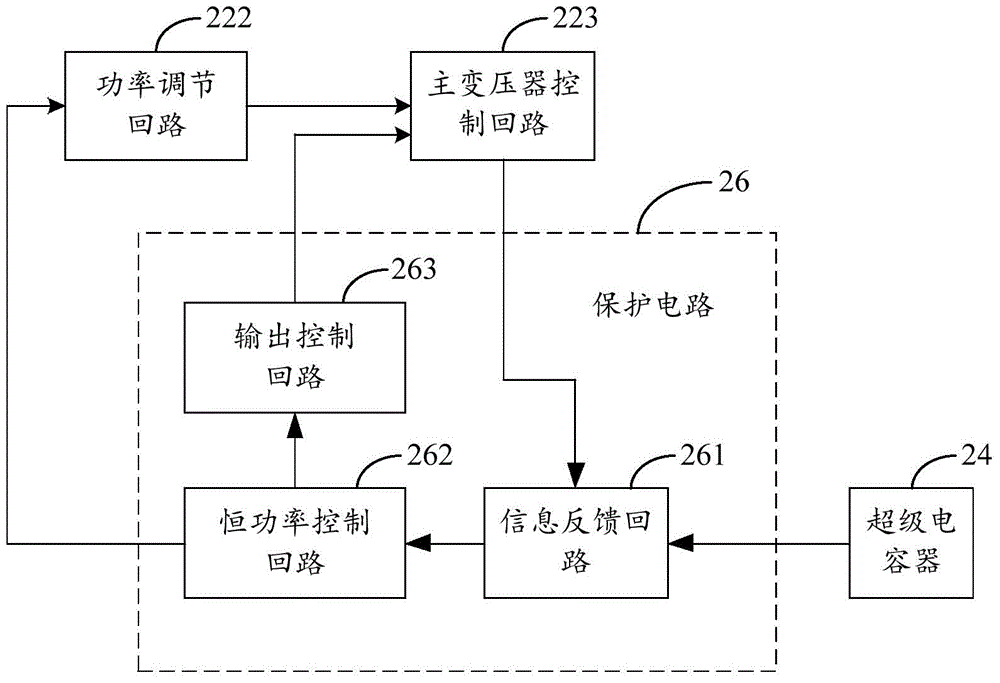
[0020] Such as figure 1 As shown, in the first embodiment, the supercapacitor charging treasure 2 of the present invention includes, but is not limited to, a first rectification circuit 21, an energy control circuit 22, a rectification output circuit 23, a supercapacitor 24, and a DC / DC limiting circuit 25 , protection circuit 26, discharge control circuit 27, and battery 28. Wherein, the input terminal of the first rectification circuit 21 is connected to the AC input voltage (such as mains), the output terminal of the first rectification circuit 21 is connected to the first input terminal of the energy control circuit 22, and the energy control circuit 22 The first output end is connected to the input end of the rectification output circuit 23, and the output end of the rectification output circuit 23 is connected to the input end (such as a connecting pin) of the supercapacitor 24 to form an AC input charging structure, that is, to the supercapacitor 24. charging structure...


PUM


Abstract

A super-capacitor power bank comprises a first rectifying circuit, an energy control circuit, a rectification output circuit, a super-capacitor, a discharge control circuit and a battery. The input end of the first rectifying circuit is connected with the alternating current input voltage, the output end of the first rectifying circuit is connected with the first input end of the energy control circuit, the first output end of the energy control circuit is connected with the input end of the rectification output circuit, the output end of the rectification output circuit is connected with the input end of the super-capacitor, the output end of the super-capacitor is connected with the input end of the discharge control circuit, and the output end of the discharge control circuit is connected with the battery. By means of the super-capacitor power bank, fast charging can be achieved.

Description

technical field [0001] The invention relates to a charging technology, in particular to a supercapacitor charging treasure. Background technique [0002] With the development of today's electronic technology, digital products such as MP3, MP4, mobile phones, and handheld computers are updated at an extremely fast speed and emerge in endlessly. In particular, mobile phones are one of the most commonly used consumer goods. Since the visibility and entertainment of mobile phones with large screens are greatly improved, their screens are constantly developing towards large or even super large screens. The continuous increase of the screen makes the power consumption of the mobile phone double, but the power of the battery cannot be doubled, resulting in shortening the use time of the mobile phone and bringing inconvenience and trouble to the user in work and life. In response to such a situation, a power bank specially used to charge mobile phones and other electronic products ...

Claims


Application Information

Patent Timeline
Patent Type & Authority Applications(China)
IPC IPC(8): H02J7/00
CPCH02J7/06H02J7/0029H02J7/0063H02J2007/0067H02J2007/10
Inventor 肖劲刘英贺国栋
Owner SHENZHEN XINGJISHENG ELECTRONICS
Learn More