
Motor and controller assembly of integrated structure

A controller, all-in-one technology, applied in the direction of electric components, connection with control/drive circuits, electrical components, etc., can solve the problem that the cable box plug-in is susceptible to wear and water corrosion, the integrated controller and motor components have a low failure rate, Reduce production efficiency and other issues to avoid rainwater damage, wear and tear damage, and improve production efficiency

Active Publication Date: 2015-03-25
商丘市奔运车业有限公司
View PDF6 Cites 5 Cited by
  • Summary
  • Abstract
  • Description
  • Claims
  • Application Information

AI Technical Summary

Problems solved by technology

[0002] At present, electric bicycles, motorcycles and tractors mostly use brushless DC motors. The functions of brushless DC motors such as speed regulation, undervoltage protection, motor overcurrent protection, brake power failure, and power display rely on Hall sensors and controllers. Realization; now the motors and controllers in most electric vehicles are installed separately in different positions of the car body, and the motors and controllers need to be connected with longer cables and more plug-ins, which will not only increase production costs and Reduce production efficiency, and the exposed cable box inserts are susceptible to abrasion and water corrosion, resulting in a high failure rate
[0003] At present, there are also controllers and motors on the market that are integrated into one structure, but the structure is unreasonable, especially in terms of water resistance. The control circuit board and Hall components are easily installed together with the motor. It is easy to touch the water, which has great potential safety hazards. Facts have proved that the failure rate of such an integrated controller and motor assembly is not lower than that of the separated type

Method used


Image

  • Motor and controller assembly of integrated structure
  • Motor and controller assembly of integrated structure
  • Motor and controller assembly of integrated structure

Examples


Embodiment Construction

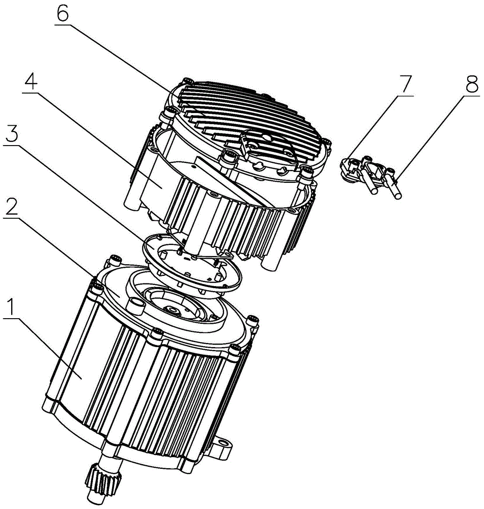
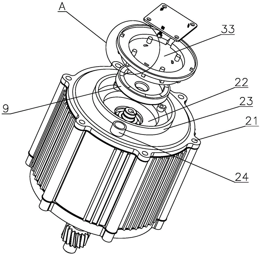
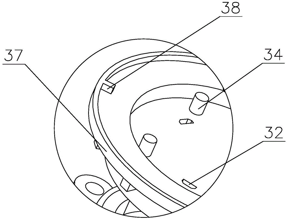
[0029] The present invention is described in further detail now in conjunction with accompanying drawing. These drawings are all simplified schematic diagrams, which only illustrate the basic structure of the present invention in a schematic manner, so they only show the configurations related to the present invention.

[0030] Such as Figure 1~6 As shown, the invention provides a motor and controller assembly of an integrated structure, including:

[0031] Motor casing 1, the rear end of the motor casing 1 is open and has a cylindrical first cavity inside, the stator, rotor and motor shaft are installed in the first cavity, and the motor casing 1 is provided with a plurality of first A threaded hole, a temperature sensor is also installed in the motor casing 1, the temperature sensor is arranged on the coil of the stator, the temperature sensor is connected with the control circuit, the electric vehicle is easy to be overloaded in the actual use process, especially in heavy...


PUM


Abstract

The invention provides a motor and controller assembly of an integrated structure. The motor and controller assembly comprises a motor casing, the rear end of the motor casing is open, a first cavity which is cylindrical is formed in the rear end of the motor casing, a stator, a rotor and a motor shaft are installed in the first cavity, and the motor casing is provided with a plurality of first threaded holes in the circumferential direction. The motor and controller assembly of the integrated structure is simple and compact in structure and reasonable in layout, a motor part and a controller part are arranged closely, the use number of cables and plugs is reduced, and therefore production cost is lowered, production efficiency is improved, the cables nearly have no exposed portion, abrasion damage caused by contact with a compartment and rain erosion are avoided, and the fault rate is reduced; meanwhile, a motor is separated from a Hall component through a plastic shell, rain erosion is avoided, and the service life and stability of the motor and a controller are guaranteed.

Description

technical field [0001] The invention relates to the technical field of motors and motor control, in particular to an integrated motor and controller assembly. Background technique [0002] At present, electric bicycles, motorcycles and tractors mostly use brushless DC motors. The functions of brushless DC motors such as speed regulation, undervoltage protection, motor overcurrent protection, brake power failure, and power display rely on Hall sensors and controllers. Realization; now the motors and controllers in most electric vehicles are installed separately in different positions of the car body, and the motors and controllers need to be connected with longer cables and more plug-ins, which will not only increase production costs and The production efficiency is reduced, and the exposure of the cable box insert is vulnerable to abrasion and water corrosion, resulting in an excessively high failure rate. [0003] At present, there are also controllers and motors on the ma...

Claims


Application Information

Patent Timeline
IPC IPC(8): H02K11/00H02K5/04H02K11/30
Inventor 唐涛丁本元梅文莱
Owner 商丘市奔运车业有限公司
Learn More