Check patentability & draft patents in minutes with Patsnap Eureka AI!

Spectral photon counting detector

A detector and time counter technology, applied in the field of spectral photon counting detectors, can solve the problem of energy estimation that has not been greatly improved

Active Publication Date: 2015-03-25
KONINKLJIJKE PHILIPS NV
View PDF5 Cites 6 Cited by
  • Summary
  • Abstract
  • Description
  • Claims
  • Application Information

AI Technical Summary

Problems solved by technology

Stochastic models have been proposed to incorporate stacking into maximum likelihood evaluation schemes, however, since the space of possible solutions is so large that the probability of the most likely solution is not significantly different from that of the least likely , so the method does not yield much improved energy estimates for

Method used


Image

  • Spectral photon counting detector
  • Spectral photon counting detector
  • Spectral photon counting detector

Examples


Embodiment Construction

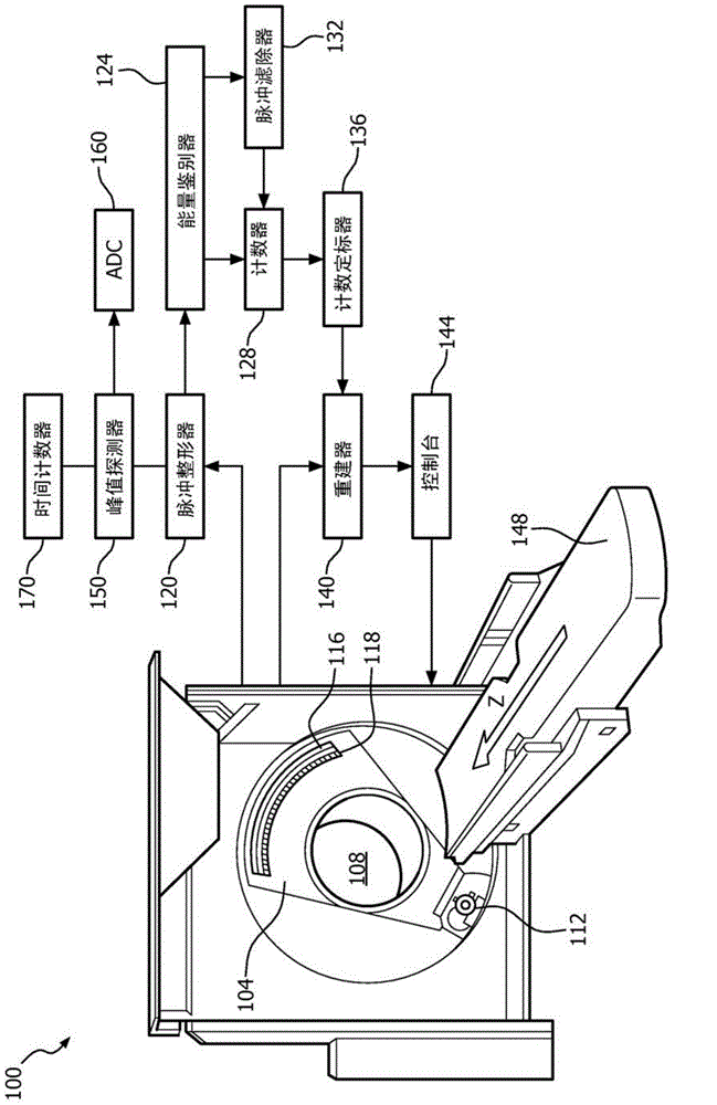
[0018] refer to figure 1 , a computed tomography (CT) system 100 includes a rotating gantry portion 104 that rotates about an examination region 108 about a longitudinal or z-axis. An X-ray source 112 , such as an X-ray tube, is supported by the rotating gantry section 104 and emits a beam of multi-energy radiation that traverses the examination region 108 .

[0019] Radiation sensitive detector 116 includes a plurality of pixels 118 that detect photons emitted by source 112 over a range of at least one hundred eighty degrees plus a fan angle. Each of the plurality of pixels 118 generates a corresponding electrical signal, such as a current or voltage, for each detected photon. Examples of suitable sensors include direct conversion detectors (eg, cadmium zinc telluride (CZT)-based detectors) and scintillator-based sensors that include a scintillator in optical communication with a photosensor.

[0020] A pulse shaper 120 processes the electrical signal and generates one or m...


PUM


Abstract

An apparatus includes a pulse shaper (120) for receiving signals indicative of detected photons and generating a plurality of pulses therefrom to form a pulse train (200) and a peak detector (150) for sampling the pulse train (200) at an output of the pulse shaper (120). The peak detector (150) includes a circuit (300) for selectively detecting and sampling a maximum (202a, b, c) and a minimum (204a, b) value of the pulse train (200). The maximum (202a, b, c) and minimum (204a, b) values sampled are then converted from analog-to-digital format via an analog-to-digital converter (160).

Description

technical field [0001] This application relates generally to spectral photon counting detectors. Although this application is described in connection with a particular application to computed tomography (CT), this application is also directed to other applications where energy resolution of detected photons having different energies is desired. Background technique [0002] Computed tomography (CT) systems include a radiation source that emits multi-energetic ionizing photons throughout an examination region. Such a system also includes a radiation sensitive detector located opposite the radiation source relative to the examination region, the radiation sensitive detector detecting photons passing through the examination region. The detector generates an electrical signal, such as a current or voltage, for each detected photon. The detector also includes electronics for energy resolving the detected photons based on the electrical signal. [0003] By way of example, the r...

Claims


Application Information

Patent Timeline
IPC IPC(8): G01T1/17
CPCG01T1/17G01N23/046G01T1/171H03M1/125
Inventor C·赫尔曼
Owner KONINKLJIJKE PHILIPS NV
Features
  • R&D
  • Intellectual Property
  • Life Sciences
  • Materials
  • Tech Scout
  • Unparalleled Data Quality
  • Higher Quality Content
  • 60% Fewer Hallucinations
Learn More