Single-excitation ultrasonic elliptical vibration micro-machining work platform
A technology of elliptical vibration and working platform, which is applied in the directions of worktable, fluid using vibration, manufacturing tools, etc., can solve the problems of ultrasonic machining resonance frequency drift, unstable processing quality, and reduced processing efficiency, so as to improve work reliability, Simple structure, stable vibration performance
- Summary
- Abstract
- Description
- Claims
- Application Information
AI Technical Summary
Problems solved by technology
Method used
Image

Examples
Embodiment Construction
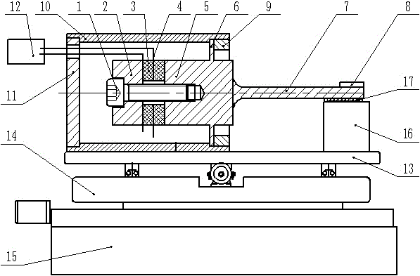
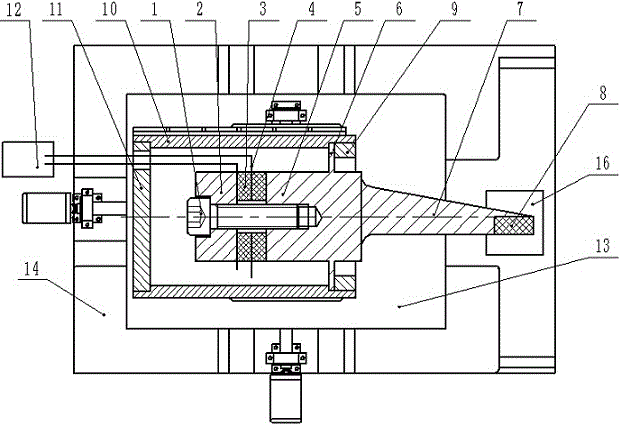
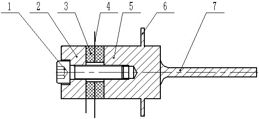
[0021] combine figure 1 , 2 , 3, and 4, the single-excitation ultrasonic elliptical vibration micromachining work platform includes a vibration isolation platform 15, a lateral mobile work platform 14 connected to the top of the vibration isolation platform 15 by bolts, and a horizontal mobile work platform 14 connected to the top of the lateral mobile work platform 14 by bolts. Longitudinal mobile working platform 13, shell unit, ultrasonic vibration transducer placed in the shell unit, ultrasonic power supply 12, elliptical vibration mode converter 7 and small working platform 8 arranged at the front end of elliptical vibration mode converter 7 . An auxiliary support 16 is arranged below the end of the elliptical vibration mode converter 7 , and a rolling support body 17 is arranged between the end of the elliptical vibration mode converter 7 and the auxiliary support 16 . The housing unit is connected above the longitudinally movable working platform 13 through bolts, and...
PUM
 Abstract
Description
Claims
Application Information