
Machining method of turbine rotor

A processing method and turbine rotor technology, applied in the field of mechanical processing, can solve the problems of turbine rotor coaxiality, roundness, poor rotation accuracy, etc., and achieve the effects of improving processing accuracy, improving coaxiality, and easy alignment

Active Publication Date: 2015-04-01
CHONGQING JIANGJIN SHIPBUILDING IND
View PDF6 Cites 6 Cited by
  • Summary
  • Abstract
  • Description
  • Claims
  • Application Information

AI Technical Summary

Problems solved by technology

[0004] Aiming at the technical problems of poor concentricity, roundness, and rotation accuracy of turbine rotors in the prior art, the present invention provides a machining method for turbine rotors. The turbine rotors processed by this machining method have good coaxiality and roundness, and improve Improve the rotation accuracy of the turbine rotor and increase the service life of the turbine rotor

Method used


Image

  • Machining method of turbine rotor
  • Machining method of turbine rotor
  • Machining method of turbine rotor

Examples


Embodiment Construction

[0070] The specific implementation manner of the present invention will be described in further detail below in conjunction with the accompanying drawings.

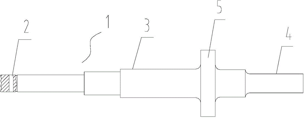
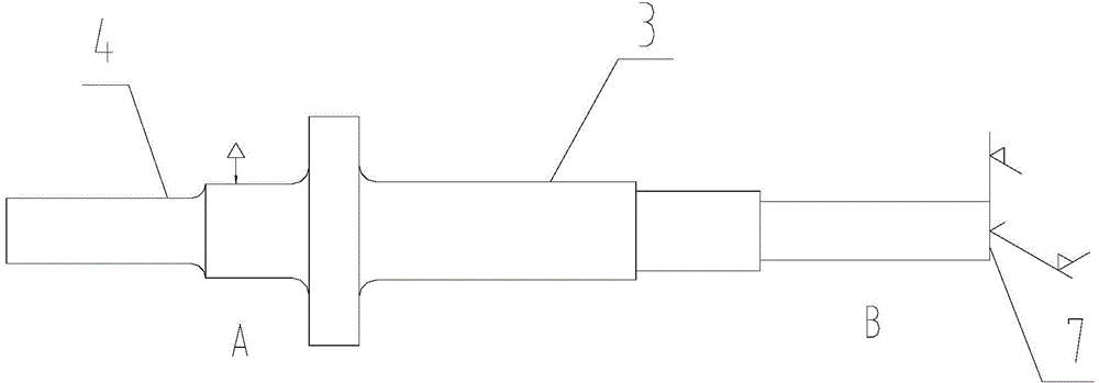
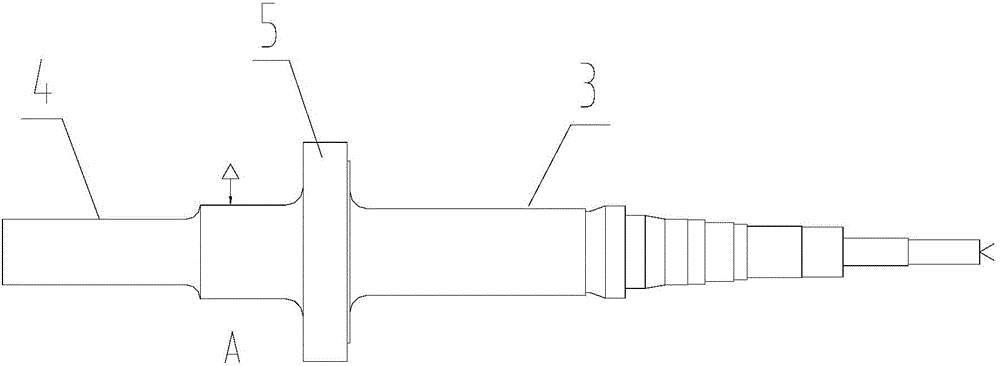
[0071] Such as Figure 1-14 As shown, a method for machining a turbine rotor includes the following steps:

[0072] a. The compressor end 3, the turbine disk 5 and the turbine end 4 of the rough turning turbine shaft 1;

[0073] b. Drill lifting hole 2, the lifting hole is used for hoisting in the subsequent heat treatment process;

[0074] c. Lift the turbine shaft 1 through the lifting hole 2, and perform heat treatment according to the specifications;

[0075] d. The compressor end 3, the turbine disk 5 and the turbine end 4 of the semi-finishing turbine shaft 1;

[0076] e. Grinding the outer circle and end face of the turbine shaft 1;

[0077] f. Align the ground outer circle and end face, finish turning the turbine shaft 1 compressor end 3, turbine disc 5 and turbine end 4;

[0078] g. Grinding and broaching th...


PUM


Abstract

A machining method of a turbine rotor comprises the following processes of step a, performing rough turning on a pressure air end, a turbine disk and a turbine end of a turbine shaft; step b, performing drilling and heat treatment on a lifting hole; step c, performing heat treatment on the turbine shaft; step d, performing half-finished turning on the pressure air end, the turbine disk and the turbine end of the turbine shaft; step e, grinding outer circles and an end surfaces; step f, aligning the ground outer circles and end surfaces and performing finish turning on the pressure air end, the turbine disk and the turbine end of the turbine shaft; step g, grinding a tongue groove positioning circle and a key groove positioning circle; step h, aligning the tongue groove positioning circle and broaching a tongue groove; step i, aligning the key groove positioning circle and milling a key groove, an air guide wheel key groove and a pressure air impeller key groove; step j, performing finish turning an air sealing groove, an oil sealing groove and a center hole; step k, grinding stages of outer circles and end surfaces; step l, performing rounding on the key groove and performing deburring and chamfering on the tongue groove; step m, installing an air sealing ring on the turbine shaft; step n, performing finish turning on the end surface of the total length of the pressure air end and performing smooth transfer and polishing on the outer circles; step o, performing finish turning on the air sealing ring and performing smooth transfer and polishing on the outer circles; step p, performing appearance inspection. According to the machining method of the turbine rotor, the rotary accuracy of the turbine rotor is improved.

Description

technical field [0001] The invention relates to the technical field of machining, in particular to a machining method for a turbine rotor. Background technique [0002] In recent years, with the advancement of technology and scientific development, on the one hand, engine products are required to be safer and more reliable in performance, more environmentally friendly, energy-saving, more economical and cheaper to use, on the other hand, due to various production materials, production factors, labor costs and other expenses The improvement of the industry, coupled with the impact of the world economy, has caused great economic pressure on many enterprises and seriously restricted the development of enterprises. The turbocharger is a high-speed running part installed on the diesel engine, and the turbine rotor is an important part of the high-speed running inside the turbocharger. For this reason, for the machining of the turbine rotor, its machining accuracy and quality mus...

Claims


Application Information

Patent Timeline
IPC IPC(8): B23P15/00B23B1/00
CPCB23P15/006
Inventor 周德贵段昌文
Owner CHONGQING JIANGJIN SHIPBUILDING IND
Learn More