
Light driven micro-fluid pump

A microfluidic and light-driven technology, which is applied in pumps, machines/engines, liquid displacement machinery, etc., can solve the problem of small driving force of electrostatic-driven micropumps, low operating frequency of heat-driven micropumps, limited output flow and Problems such as back pressure, to achieve the effect of large driving capacity, high operating frequency and fast response speed

Inactive Publication Date: 2015-04-01
CHANGZHOU UNIV
View PDF7 Cites 18 Cited by
  • Summary
  • Abstract
  • Description
  • Claims
  • Application Information

AI Technical Summary

Problems solved by technology

For example, the driving voltage of the piezoelectric-driven micropump is high; the driving force of the electrostatic-driven micropump is small, and the deformation displacement is small; the operating frequency of the thermal-driven micropump is low, which limits its output flow and back pressure.

Method used


Image

  • Light driven micro-fluid pump
  • Light driven micro-fluid pump
  • Light driven micro-fluid pump

Examples


Embodiment Construction

[0031] The present invention is described in further detail now in conjunction with accompanying drawing. These drawings are all simplified schematic diagrams, which only illustrate the basic structure of the present invention in a schematic manner, so they only show the configurations related to the present invention.

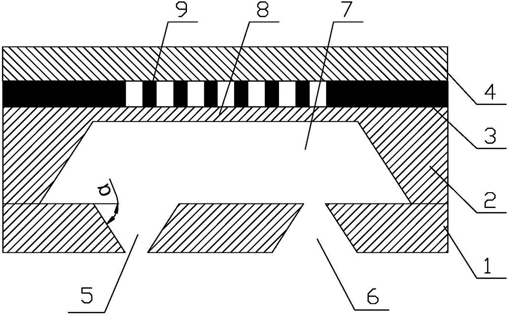
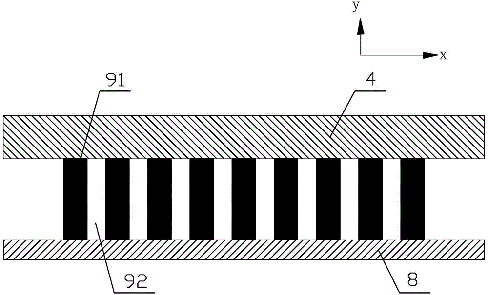
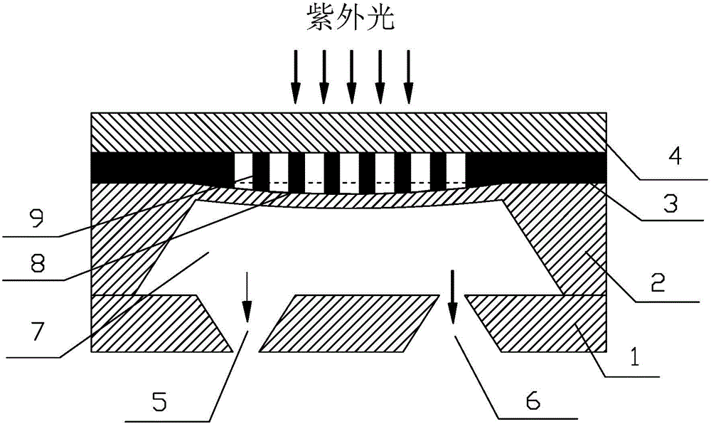
[0032] Such as figure 1 As shown, it is a schematic diagram of an embodiment of the light-driven microfluidic pump of the present invention. The present invention includes an inlet and outlet layer 1, a pump chamber layer 2, a micro wire grid array driving unit 3 and a substrate 4 in sequence from bottom to top.

[0033] The inlet and outlet layer 1 provides an inlet 5 and an outlet 6 for transferring liquid. The inlet 5 is a tapered mouth with a wide top and a narrow bottom, and the outlet 6 is just the opposite. It is a tapered mouth with a narrow top and a wide bottom. The shape of the inlet 5 and outlet 6 , the same size, but upside down, as follows figu...


PUM


Abstract

The invention relates to a light driven micro-fluid pump. The light driven micro-fluid pump converts between light energy and mechanical energy. The light driven micro-fluid pump comprises an outlet / inlet layer, a pump cavity layer, a micro-wire grid array drive unit and a substrate in sequence from the bottom to top; the outlet / inlet layer is provided with an inlet and an outlet; the pump cavity layer comprises a pump cavity and a deformable vibrating diaphragm; the micro-wire grid array drive unit comprises a micro-wire grid array of which the period is hundreds of nanometers, the micro-wire grid array is composed of grid ridges and grid valleys, and the micro-wire grid array is a shape memory material azobenzene liquid crystal elastomer. The light driven micro-fluid pump periodically changes the irradiation light type and light intensity and is capable of precisely controlling the periodic change of the pump cavity volume of the micro-fluid pump so as to generate continuous differential flow. The light driven micro-fluid pump has advantages of fast respond speed, high working frequency, small energy consumption, large drive quantity and the like; the light driven micro-fluid pump is capable of precisely controlling the flow rate and capable of being used for the cell separation, micro-feeding of fluid, micro-injection of medicine, micro-chemical analysis and the like fields; the apparatus manufacturing can use an MEMS processing technique compatible with an IC manufacturing technique, and the apparatus manufacturing is suitable for batch production.

Description

technical field [0001] The invention relates to a light-mechanical energy conversion micro-drive device, in particular to a light-driven micro-fluid pump. Background technique [0002] Microfluidic systems include microfluidic pumps, microvalves, microsensors, microsprays, and microchannels, among which microfluidic pumps are a key device in microfluidic systems. [0003] According to the different driving methods, microfluidic pumps can be divided into piezoelectric driving type, electrostatic driving type, shape memory alloy driving type, thermal driving type and other types. The above-mentioned driving methods each have different advantages, but also have their own shortcomings. For example, the driving voltage of the piezoelectric-driven micropump is relatively high; the driving force of the electrostatic-driven micropump is small, and the deformation displacement is small; the operating frequency of the heat-driven micropump is low, which limits its output flow and bac...

Claims


Application Information

Patent Timeline
Patent Type & Authority Applications(China)
IPC IPC(8): F04B43/02F04B45/04
Inventor 贾克辉
Owner CHANGZHOU UNIV
Learn More