Mine water pump pressure relief device

A technology of pressure relief device and water pump, which is applied in the direction of valve device, parts of pumping device for elastic fluid, pump components, etc. It can solve the problems of damage to water supply equipment, motor burnout, motor heating, etc., and prevent overload operation , Reduce maintenance costs, improve the effect of service life

Inactive Publication Date: 2015-04-01
SICHUAN HUAYINGSHAN COAL IND CO LTD LIZIYA MINE
View PDF5 Cites 6 Cited by
  • Summary
  • Abstract
  • Description
  • Claims
  • Application Information

AI Technical Summary

Problems solved by technology

[0002] Underground coal mine production and dust control water often adopt the dynamic pressure water supply method. In the process of water use, due to the different needs of on-site work, such as the reduction or stop of dust control and production water, it will suddenly cause changes in the amount of water used, which will cause As a result, the water output of the water pump becomes smaller or the water cannot be discharged, which will cause the water to circulate in the pump, and the water temperature in the pump body will rise, and the temperature of the pump body will also rise accordingly, which will cause damage to the water pump. The motor heats up, and eventually the motor burns out. The common sheet valve currently used to discharge excess water requires manual operation, and cannot be controlled automatically. It will damage the water supply equipment in time, increase the maintenance cost and labor cost of the water supply equipment, and affect the normal production. Therefore, designing a water pump pressure relief device is an important way to reduce production costs, ensure water supply quality, and improve production efficiency.

Method used


Image

  • Mine water pump pressure relief device
  • Mine water pump pressure relief device
  • Mine water pump pressure relief device

Examples


Embodiment Construction

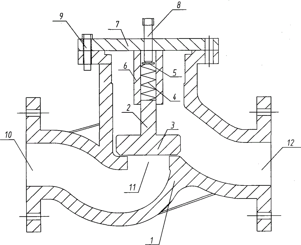
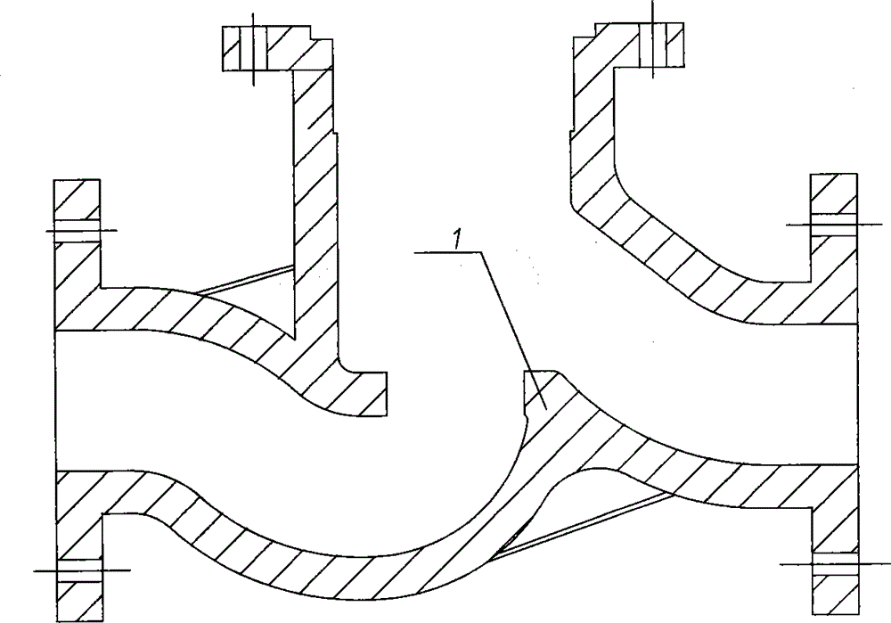
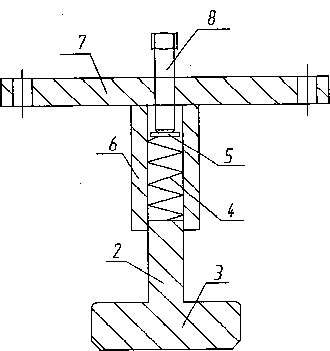
[0010] Below in conjunction with accompanying drawing, the present invention will be further described, as figure 1 , figure 2 , image 3 Shown: The mine water pump pressure relief device includes valve body 1, valve disc 2, valve disc head 3, spring 4, baffle plate 5, cylinder 6, valve cover 7, screw rod 8, bolt 9, water inlet 10, center Hole 11, water outlet 12.

[0011] Such as figure 1 , figure 2 , image 3 As shown, the valve body 1 is cast, the diameter of the water inlet 10 and the water outlet 12 is 50mm, the diameter of the middle hole 11 is 30mm, the valve disc 2 is processed into a convex shape with a length of 30mm, and the valve disc head 3 The diameter is 60mm and the height is 10mm. The diameter of the bonnet 7 is 123mm and the height is 10mm. Four M14 threaded holes are evenly processed on its circumference, and one M12 threaded hole is processed in the middle. The cylinder 6 is welded on the center of the bonnet 7 , the inner diameter of the cylinder 6...


PUM


Abstract

The invention discloses a mine water pump pressure relief device, including a valve body, a valve disk, a valve disk head, a spring, a baffle, a cylinder, a bonnet, a lead screw, a bolt, a water inlet, a mesopore and a water outlet, wherein the cylinder is welded onto the bonnet; the spring is installed in the cylinder as a motion track of the valve disk; the valve disk head of the valve disk is pressed on the mesopore; the bonnet is fixedly connected to the valve body by the bolt; the lead screw is screwed into a central threaded hole in the bonnet to be pressed against the baffle; the pressure of the spring is adjusted by the screwing stroke of the lead screw; the valve disk is set with a rated working pressure to be tightly pressed against the mesopore to block a channel; when water pressure in a water outlet pipe is more than the rated working pressure of the valve disk, the valve disk is pushed by the water pressure to move upwards to open the mesopore channel and communicate the water inlet with the water outlet, and thereby achieve pressure relief of a water pump. The mine water pump pressure relief device has the advantages of being simple in structure, achieving good overload protection, effectively avoiding the device from overload operation, improving the service life of the device, and reducing the maintenance cost of the device.

Description

technical field [0001] The invention relates to coal mine water equipment, in particular to a mine water pump pressure relief device. Background technique [0002] Underground coal mine production and dust control water often adopt the dynamic pressure water supply method. During the water use process, due to the different needs of on-site work, such as the reduction or stop of dust control and production water, it will suddenly cause changes in water consumption, which will cause As a result, the water output of the water pump becomes smaller or the water cannot be discharged, which causes the water to circulate in the pump, and the water temperature in the pump body rises, and the temperature of the pump body also rises, which will cause damage to the water pump. The motor heats up, and eventually the motor burns out. The common flap valve currently used to discharge excess water requires manual operation, and cannot be controlled automatically. In time, the water supply ...

Claims


Application Information

Patent Timeline
Patent Type & Authority Applications(China)
IPC IPC(8): F16K1/32F04B53/10
CPCF16K17/06F04B53/102F16K17/164
Inventor 马文峰任刚卢运海周鸽李健魏波张浩乙郭富生
Owner SICHUAN HUAYINGSHAN COAL IND CO LTD LIZIYA MINE
Why Eureka
Try Eureka