Cable fault detection and analysis method

An analysis method and technology for cable faults, applied in directions such as fault locations, which can solve problems such as large errors in intercepted frequency bandwidth and numerical errors.

Active Publication Date: 2015-04-01
GAUSS ELECTRONICS TECH
View PDF3 Cites 19 Cited by
  • Summary
  • Abstract
  • Description
  • Claims
  • Application Information

AI Technical Summary

Problems solved by technology

The transmission rate calculation method involved in this application is to calculate the bandwidth when the entire impedance spectrum curve decays to the minimum value, and sometimes, with the increase of the test frequency, the cable impedance spectrum is basically close to the

Method used


Image

  • Cable fault detection and analysis method
  • Cable fault detection and analysis method
  • Cable fault detection and analysis method

Examples


Embodiment 1

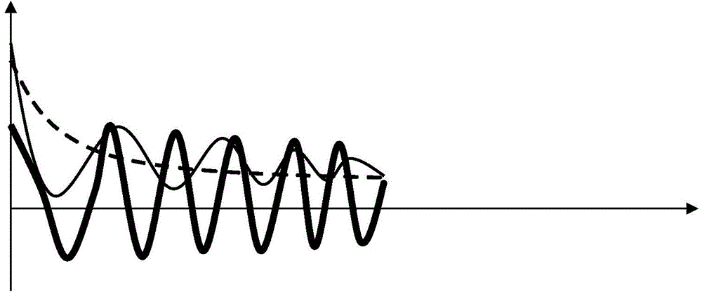
[0056] Such as figure 1 , figure 2 shown. Fault detection and analysis for 35kV, 11km long XLPE cable with remote short circuit, including the following steps.

[0057] The first step is to apply a sweep signal with a frequency range of 0-500MHz and a step value of 0.1Hz to the cable under test, and then collect the voltage time domain signal corresponding to each sweep frequency input signal and the current flowing through the cable insulation layer to form a loop Time-domain signal, and calculate the frequency-domain impedance and phase of the cable, and draw the continuous impedance-frequency curve Z(f) and phase-frequency curve Φ(f), such as figure 1 shown.

[0058] In the second step, on the phase-frequency curve Φ(f) drawn in the first step, find the frequency f corresponding to any two adjacent phase zero points 11 =20.1kHz, f 22 =28.2kHz, calculate the frequency difference Δf=|f 11 -f 22 |=8.1kHz, then substitute the frequency difference Δf into the formula V ...

Embodiment 2

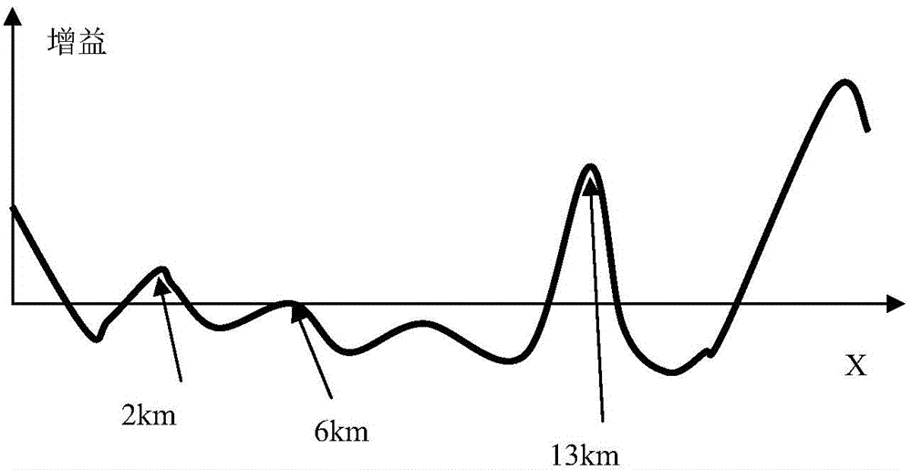
[0082] Such as image 3 , Figure 4 shown. Carry out fault detection and analysis for 35kV, 80km long, XLPE cables, including the following steps.

[0083] The first step is to apply a sweep signal with a frequency range of 0-500MHz and a step value of 0.1Hz to the cable under test, and then collect the voltage time domain signal corresponding to each sweep frequency input signal and the current flowing through the cable insulation layer to form a loop Time-domain signal, and calculate the frequency-domain impedance of the cable, and draw a continuous impedance-frequency curve.

[0084] The second step is to find the frequency f corresponding to any two adjacent impedance peak points on the impedance frequency curve drawn in the first step 11 =2.66kHz, f 22 =3.91kHz, calculate the frequency difference Δf=|f 11 -f 22 |=1.25kHz, then substitute the frequency difference Δf into the formula V r =(1+ε)D×2×Δf / V 0 =(1+1%)80000×2×1.25×10 3 / 300×10 6 , calculate the signal re...

Embodiment 3

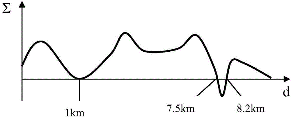
[0089] Such as Figure 5 , Figure 6 shown. Carry out fault detection and analysis for 35kV, 5km long, XLPE cables, including the following steps.

[0090] The first step is to apply a sweep signal with a bandwidth of 1GHz and a step value of 10Hz to the tested cable, and then collect the voltage time domain signal corresponding to each sweep frequency input signal and the current time domain signal flowing through the cable insulation layer to form a loop, And calculate the frequency domain impedance and phase of the cable, and draw the continuous impedance frequency curve and phase frequency curve.

[0091] The second step is to find the frequency f corresponding to any two adjacent impedance peak points on the impedance frequency curve drawn in the first step 11 =103.75kHz, f 22 =118.96kHz, calculate the frequency difference Δf=|f 11 -f 22 |=15.21kHz; On the phase frequency curve drawn in the first step, find the frequency f' corresponding to any two adjacent phase ze...


PUM

PropertyMeasurementUnit
Equivalent capacitanceaaaaaaaaaa

Abstract

The invention discloses a cable fault detection and analysis method. According to the method, an impedance frequency spectrum and a phase frequency spectrum of a cable are taken as basis, subsection characteristic impedance on an impedance frequency spectrum attenuation trend curve is calculated with a subsection interception method, an equation of equivalent impedance is established, R, L, G and C parameters of cable transmission impedance are calculated, a transmission impedance model based on R, L, G and C parameters is obtained, an error distance graph with a cable distance length serving as a variable is obtained through error calculation and comparison of the transmission impedance model and the tested impedance frequency spectrum and phase frequency spectrum, finally, local zero points on the error distance graph are analyzed, and fault detection and fault type identification are realized. Compared with the prior art, on the basis of a relative signal transmission rate calculation method with low calculation difficulty and high calculation accuracy, accurate fault positioning and multi-point fault positioning can be realized, and the fault type identification can be realized.

Description

technical field [0001] The invention relates to a cable fault detection and analysis method, in particular to a cable fault detection and analysis method based on a signal relative transmission rate calculation method with low calculation difficulty and high calculation accuracy. Background technique [0002] Cables are widely used in power transmission, communication, aviation, communication, power supply and distribution and other fields. As the statistics and understanding of cable faults continue to deepen, the detection technology for cables is also constantly improving. Common faults of cables include sheath rupture, shielding layer rupture, water ingress, conductor exposure, sprain, etc. These faults all occur between the conductor and the sheath grounding wire, or between the conductor and the shielding layer, or between the multi-core conductor and the conductor. between. [0003] The method based on withstand voltage analysis is a common method for cable insulatio...

Claims


Application Information

Patent Timeline
IPC IPC(8): G01R31/08
Inventor 张建张方荣尹娟高兴琼王苏
Owner GAUSS ELECTRONICS TECH
Why Eureka
Try Eureka