A supporting structure of 750kv lead-out wires on the network side of UHV converter transformer

A converter transformer, lead wire technology, applied in the direction of transformer/inductor coil/winding/connection, preventing/reducing unwanted electrical/magnetic influence, etc., to reduce self-weight, reduce oil consumption, flexible connection and layout Effect

Active Publication Date: 2016-06-22
CHINA XD ELECTRIC CO LTD +1
View PDF5 Cites 0 Cited by
  • Summary
  • Abstract
  • Description
  • Claims
  • Application Information

AI Technical Summary

Problems solved by technology

[0002] With the rapid development of DC transmission technology, the scope of power transfer in my country is increasing day by day. At present, the grid-side voltage of existing domestic converter transformers is up to 500kV, and DC transmission projects in some areas need to be connected to 750kV lines on the grid side. The insulation level of the grid side of the high-voltage converter transformer needs to meet the requirements of 750kV. According to the overall layout of the converter station of the DC transmission project in my country and the structural characteristics of the converter transformer itself, compared with the previous method of leading the lead wires of the 750kV AC transformer from the box wall, it cannot meet this requirement. According to actual requirements, the 750kV lead-out wires on the side of the converter transformer need to be led out from the fuel tank cover

Method used


Image

  • A supporting structure of 750kv lead-out wires on the network side of UHV converter transformer
  • A supporting structure of 750kv lead-out wires on the network side of UHV converter transformer

Examples


Embodiment Construction

[0020] The present invention will be further described in detail below with reference to the accompanying drawings, which is an explanation rather than a limitation of the present invention.

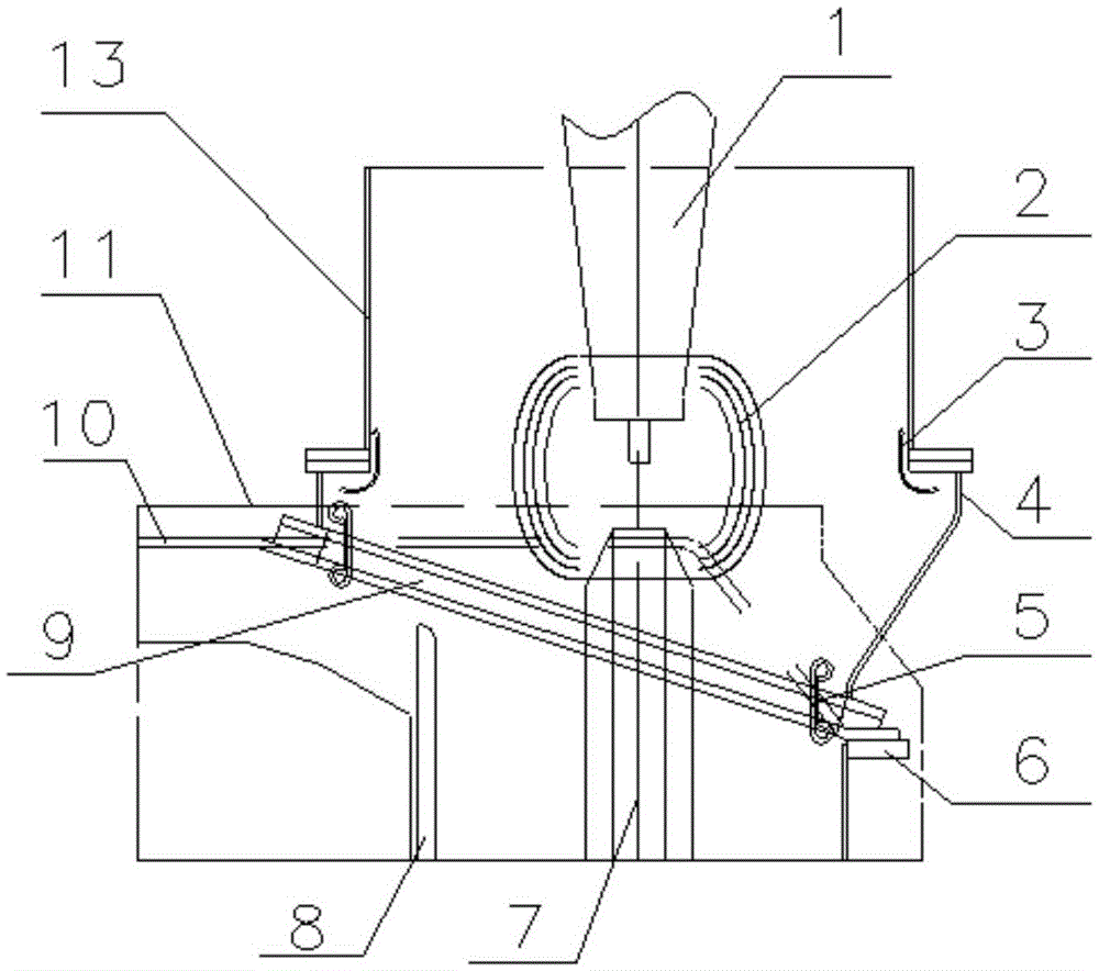
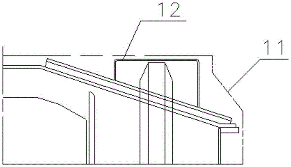
[0021] The present invention is a supporting structure of 750kV lead wire on the grid side of UHV converter transformer, such as figure 1 As shown, it includes a box cover 10 that is set above the edge 6 of the converter transformer box, an upper flange 9 of the box cover, and an inclined raised seat 4 and a straight raised seat 13 that are sequentially connected to the upper flange 9 of the box cover; The edge of 10 slopes downward to connect with the converter box edge 6. The upper flange 9 of the box cover is arranged on the inclined part of the box cover 10; the top end of the inclined riser 4 is horizontally connected to the straight riser 13, and the bottom end is inclined to the box. The cover flange 9 is connected; the diameter of the straight raised seat 13 is smaller than the top d...


PUM


Abstract

The invention provides an extra-high voltage converter transformer network side 750kV outgoing line matching structure which is simple in structure, good in insulating property and convenient to transparent. The extra-high voltage converter transformer network side 750kV outgoing line matching structure comprises a box cover higher than the edge of a converter transformer box, a flange on the box cover, and an inclined lifting seat and a straight lifting seat which are connected sequentially on the flange on the box cover; the edge of the box cover is inclined downwards and is connected to the edge of the converter transformer box; the flange on the box cover is arranged on the inclined part of the box cover; the top end of the inclined lifting seat is connected horizontally with the straight lifting seat, the bottom end of the inclined lifting seat is arranged obliquely and is connected to the flange on the box cover; the diameter of the straight lifting seat is smaller than that of the top end of the inclined lifting seat, and the diameter of the top end of the inclined lifting seat is larger than that of the bottom end; the side, close to the box cover, of the bottom end is higher than the side close to the edge of the converter transformer box; the side wall, close to the edge of the converter transformer box, of the inclined lifting seat is arranged obliquely outwards; the network side outgoing line is lead out vertically from the flange on the box cover, the end of the network side outgoing line is lower than a transportation outer limit outline; the network side outgoing line is connected to a network side sleeve or external lead by a voltage sharing device arranged in the inclined lifting seat.

Description

Technical field [0001] The invention relates to the technical solution field of converter transformers, in particular to a supporting structure of a 750kV lead wire on the grid side of an ultra-high voltage converter transformer. Background technique [0002] With the rapid development of DC transmission technology, the scope of power transfer in China is increasing. At present, the current domestic converter transformer has a grid-side voltage of up to 500kV, while DC transmission projects in some areas require 750kV lines to be connected to the grid. The grid-side insulation level of the high-voltage converter transformer needs to meet the requirements of 750kV. According to the overall layout of the converter station of China's DC transmission project and the structural characteristics of the converter transformer itself, compared with the previous method of 750kV AC transformer lead wire drawn from the box wall, this cannot be met. The actual requirement requires that the 750...

Claims


Application Information

Patent Timeline
Patent Type & Authority Patents(China)
IPC IPC(8): H01F27/29H01F27/36H01F27/32
Inventor 李红桥王涛石燕英刘燕佘海智
Owner CHINA XD ELECTRIC CO LTD
Why Eureka
Try Eureka