
Exhaust gas turbine with closed nozzle ring

A technology for exhaust gas turbines and nozzle rings, applied to stators, engine components, machines/engines, etc., can solve problems such as gaps and weakened seals

Active Publication Date: 2017-03-22
TURBO SYST SWITZERLAND LTD
View PDF7 Cites 0 Cited by
  • Summary
  • Abstract
  • Description
  • Claims
  • Application Information

AI Technical Summary

Problems solved by technology

However, different thermal expansions during operation of the exhaust gas turbine can lead to weakening of the seal or even gaps due to the resulting plastic deformation.

Method used


Image

  • Exhaust gas turbine with closed nozzle ring
  • Exhaust gas turbine with closed nozzle ring
  • Exhaust gas turbine with closed nozzle ring

Examples


Embodiment Construction

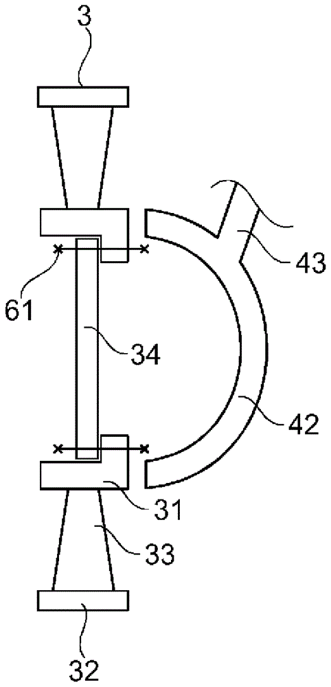
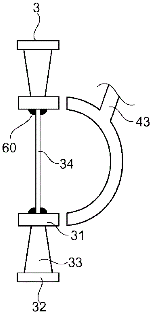
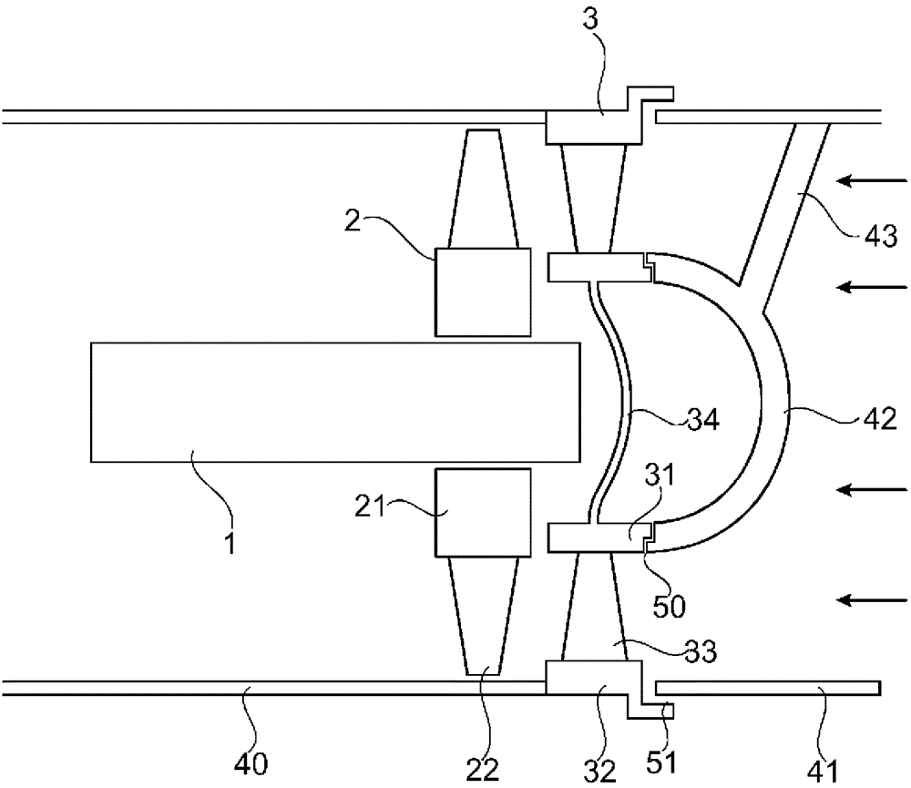
[0024] figure 1 An axially flowing exhaust gas turbine is shown in the schematic illustration of a shaft section. The outward orientation of the exhaust gas turbine is limited by the two-part outer gas inlet housing 40 , 41 which is tubular in shape. The turbine wheel 2 is arranged concentrically in the outer gas inlet housings 40 , 41 and is mounted rotatably by the shaft 1 . The turbine wheel 2 has a hub body 21 and rotor blades 22 . The cylindrical hub body 21 is arranged axially around the shaft 1 . The rotor blades 22 are fixed on the outer cylindrical surface of the hub body 21 and distributed in the circumferential direction. In order to ensure collision-free rotation of the turbine wheel 2 , the length of the rotor blades 22 is dimensioned such that there is a gap between the radially outer ends of the rotor blades 22 and the outer gas inlet housings 40 , 41 . Upstream of the turbine wheel 2 there is a nozzle ring 3 which is arranged concentrically to the turbine w...


PUM


Abstract

The invention relates to an exhaust gas turbine having a shaft (1) and a turbine wheel (2), and which has an internally closed nozzle ring (3). The nozzle ring (3) has guide blades (33) and an inner ring (31) that lies radially inside in relation to the guide blade (33). An inner surface of the nozzle ring (3) bounded by the inner ring (31) is filled out by a cover (34) and sealed in regard to the exhaust gas flow, such that the inner surface is closed in regard to a throughflow of the exhaust gas. Thus, the sealing point between the nozzle ring (3) and an inner gas inlet housing (42) is omitted and is transferred to a technically simpler seal between the nozzle ring (3) and the cover (34).

Description

technical field [0001] The invention relates to the field of exhaust gas turbines with axial inflow. It relates to an exhaust gas turbine with a turbine wheel carried by a shaft, a nozzle ring and a gas inlet housing. Background technique [0002] Exhaust gas turbines are used in particular in power turbines and in exhaust gas turbochargers. The exhaust gas from the internal combustion engine is fed to the exhaust gas turbine. Since the exhaust gas is not fully expanded, the energy still present in the exhaust gas can partly be converted into rotational energy of the exhaust gas turbine. In an axially inflow exhaust gas turbine, the exhaust gas is guided axially via the outer gas inlet housing to a rotatably mounted turbine wheel positioned in the outer gas inlet housing. The turbine wheel comprises a hub body and rotor blades fastened to the hub body, at which the exhaust gas flow performs work and thereby partially converts the energy of the exhaust gas into rotational ...

Claims


Application Information

Patent Timeline
Patent Type & Authority Patents(China)
IPC IPC(8): F01D9/04
Inventor C.克雷恩坎普M.贾鲁塞M.乔霍D.豪塞M.里奇纳
Owner TURBO SYST SWITZERLAND LTD
Learn More