
Numerical control winding machine tool of vertical iron core

An iron core and winding technology, which is applied in the field of vertical iron core CNC winding machine tool system, can solve the problems affecting the cross-sectional shape of the iron core, the compactness of the iron core, the production efficiency and production quality to be improved, and the difficulty in ensuring the center position of the silicon steel strip and other problems to achieve the effect of ensuring the winding tension and overcoming the gravity interference of the pressing arm

Inactive Publication Date: 2015-04-08
UNIV OF JINAN
View PDF7 Cites 2 Cited by
  • Summary
  • Abstract
  • Description
  • Claims
  • Application Information

AI Technical Summary

Problems solved by technology

However, because the current theory of coiled iron core transformers is not perfect enough, many manufacturers are producing coiled iron cores after modifying the original equipment. Compactness, production efficiency and production quality also need to be improved

Method used


Image

  • Numerical control winding machine tool of vertical iron core
  • Numerical control winding machine tool of vertical iron core
  • Numerical control winding machine tool of vertical iron core

Examples


Embodiment Construction

[0020] The present invention will be specifically described below in conjunction with the accompanying drawings and embodiments.

[0021] The invention is an auxiliary machine for the winding work of a multi-stage ladder type or R-type iron core of a winding core distribution transformer.

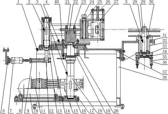
[0022] figure 1 Shown is a schematic front view of the structure of the present invention.

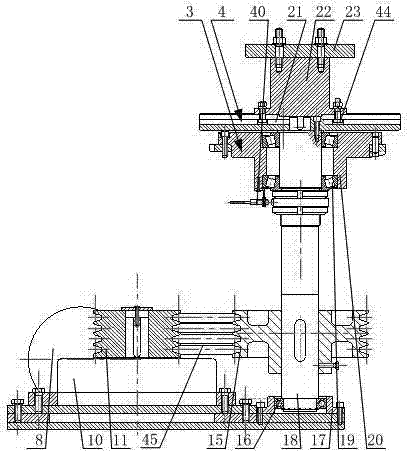
[0023] figure 2 Shown is a schematic top view of the structure of the present invention.

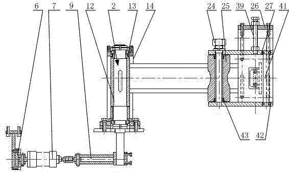
[0024] The present invention includes a bed body 1, a pressing arm mechanism 2, a spindle drive assembly 3, a faceplate mandrel assembly 4, and a damping discharge mechanism 5. The spindle drive assembly 3 is installed in the bed body 1, and the faceplate mandrel assembly 4 is installed on the top of the spindle drive assembly 3, the pressing arm mechanism 2 is installed on the workbench 37, and the damping discharge mechanism 5 is installed on the side of the bed body 1.

[0025] image 3 Shown is a sch...


PUM


Abstract

The invention discloses a numerical control winding machine tool of a vertical iron core. the numerical control winding machine tool comprises a tool body, a pressure arm mechanism, a main shaft transmission component, a faceplate core mold component and a damping discharge mechanism, wherein the pressure arm mechanism is positioned at the top end in the tool body, and consists of a rotating shaft, a bearing, a swinging arm bracket, a push rod, a cylinder, a cylinder bracket, a swinging arm and a core mold pressure roller; the main shaft transmission component is positioned at the top end in the tool body, and consists of a motor, a speed reducer, a belt wheel, a main shaft, a bearing and a bearing bracket; the faceplate core mold component is mounted at the top end of the main shaft transmission component, and consists of a core mold, a mold base and a faceplate; and the damping discharge mechanism is mounted on the side surface of the tool body, and consists of a shaft, a bearing, a thread shaft and a bracket. The numerical control winding machine tool can be applied to the winding operation of multistage step-shaped or R-shaped iron cores of wound iron core distribution transformers, and can effectively improve the material utilization rate and the lamination coefficient.

Description

technical field [0001] The invention relates to a vertical iron core numerically controlled winding machine tool equipment, in particular to a vertical iron core numerically controlled winding machine tool system for winding iron core distribution transformers with multi-stage ladder type or R-shaped iron core. Background technique [0002] The coiled iron core transformer utilizes the magnetic properties of high magnetic permeability and low loss cold-rolled silicon steel sheet, adopts rolling process to reduce joints, and makes the magnetic flux distribution tend to be uniform. Since the wound core transformer utilizes the orientation of the silicon steel sheet, the no-load loss is low. At the same time, the silicon steel sheet has no cross-cutting process, which eliminates the quality fluctuation caused by manual lamination, stacking, disassembly and insertion of the iron yoke, and the corners There is less waste, and the material utilization rate is higher than that of S9...

Claims


Application Information

Patent Timeline
Patent Type & Authority Applications(China)
IPC IPC(8): B21D11/06H01F41/02
CPCB21D11/06H01F41/0206
Inventor 陈乃建曹树坤李长春宋方臻孙选李映君陈洪堂
Owner UNIV OF JINAN
Learn More