Al technical title is built by PatSnap Al team. It summarizes the technical point description of the patent document.
A particle separation, low-speed technology, used in centrifuges with rotating drums, centrifuges, etc., can solve problems such as easy failure and complex process
Active Publication Date: 2019-10-18
安徽益必生物科技有限公司
View PDF10 Cites 1 Cited by
Summary
Abstract
Description
Claims
Application Information
AI Technical Summary
This helps you quickly interpret patents by identifying the three key elements:
Problems solved by technology
Method used
Benefits of technology
Problems solved by technology
[0003] Although ultracentrifugation can solve the problem of recovery of biological or non-biological microscopic particles suspended in liquid to a certain extent, the sample preparation process and experimental operation of ultracentrifugation, especially the process of density gradient centrifugation are very complicated and prone to failure. This case provides A new separation method was developed to solve this technical problem
Method used
Image
Click on the blue label to locate the original text in one second.
Reading with bidirectional positioning of images and text.
Examples
Embodiment 1
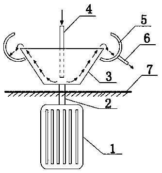
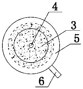
[0024] Embodiment 1, see Figure 1-2 , the present invention provides a technical solution: a low-speed micro-particle separation device, including a motor 1, a transmission shaft 2, a sample separation cup 3, a liquid inlet pipe 4, a sample collection tank 5, a liquid discharge pipe 6 and a sealing isolation layer 7 , the motor 1 is connected to the sample separation cup 3 through the transmission shaft 2, and the sample separation cup 3 is separated from the motor 1 by a sealing isolation layer 7, and the periphery of the cup opening of the sample separation cup 3 is provided with an annular A sample collection tank 5, the bottom of the sample collection tank 5 is provided with one or several funnel-shaped openings, and is connected to a liquid discharge pipe 6, and the inner cavity of the sample separation cup 3 is provided with a liquid inlet pipe 4 along the up and down direction;
[0025] The sealing isolation layer 7 can be extended as a housing or a flat plate that wra...
PUM
Abstract
The invention discloses a low-rotation-speed micro-particle separation device. According to the design, the centrifugal force is used for overcoming self-gravity of the liquid, so that the centrifugalforce can climb upwards from bottom to top in the sample separation cup, a thin layer is formed on the inner wall, a special limiting space is formed by the liquid thin layer, micro particles are subjected to polarization brownian motion, differential migration is realized, the aim of separating the micro particles is achieved, the device comprises a motor, a transmission shaft, a sample separation cup, a liquid inlet pipe, a sample collection tank, a liquid discharge pipe and a sealing isolation layer, wherein the motor is connected with the sample separation cup through the transmission shaft. The method can be used in the industrial field, such as production of colloidal gold particles, diamond sorting for cutting, high-grade coal, mineral refining and the like, and can also be used inthe field of biological medical treatment, and microorganisms, the method can be used for separating and analyzing different types of microorganisms, and is simple in separation means, high in success rate, wide in application range and high in practicability.
Description
technical field [0001] The invention relates to the technical field of micro-particle separation, in particular to a low-speed micro-particle separation device. Background technique [0002] The size of chemical molecules reaches the range of colloidal particles, which can form a stable suspension (that is, colloidal solution); even if some biological or non-biological particles are slightly larger than the size of colloidal particles, the suspension is relatively stable and needs to stand for a long time Time can settle down. In order to quickly separate tiny particles like proteins from quasi-stable suspensions, Swedish scholar Theodor Svedberg invented the ultracentrifuge in the 1920s. The purpose of his original invention was not only to separate proteins, but also to It is important to measure protein molecular weight. In any case, ultracentrifugation has become a classic means of separating colloidal particles and other biological and non-biological tiny particles. Th...
Claims
Application Information
Patent Timeline
Application Date:The date an application was filed.
Publication Date:The date a patent or application was officially published.
First Publication Date:The earliest publication date of a patent with the same application number.
Issue Date:Publication date of the patent grant document.
PCT Entry Date:The Entry date of PCT National Phase.
Estimated Expiry Date:The statutory expiry date of a patent right according to the Patent Law, and it is the longest term of protection that the patent right can achieve without the termination of the patent right due to other reasons(Term extension factor has been taken into account ).
Invalid Date:Actual expiry date is based on effective date or publication date of legal transaction data of invalid patent.