Adhesive tape cutting device

A technology of cutting device and adhesive tape, which is applied in the field of electric power system, can solve the problems of electrician discomfort, box crowding, endangering electrician's health, etc., and achieve the effects of accelerating efficiency, ensuring comfort, and improving practicability

Inactive Publication Date: 2015-04-08
宜宾市净源电子科技有限公司
View PDF0 Cites 4 Cited by
  • Summary
  • Abstract
  • Description
  • Claims
  • Application Information

AI Technical Summary

Problems solved by technology

[0003] However, during the winding process of insulating tape and fireproof tape, due to the certain toughness and elasticity of the tape, after the wrapping is completed, the connection between the tape wound on the thread and the tape body is handled. The ordinary electrician's operation method is generally through Brutely tear it or bite it off with your teeth. During the tearing process of the former, there will be a long section of over

Method used


Image

  • Adhesive tape cutting device

Examples


Embodiment 1

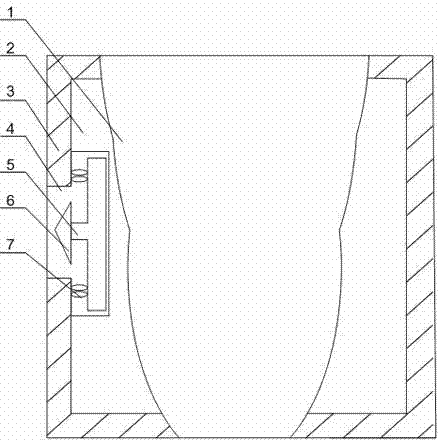
[0020] Such as figure 1 As shown, this embodiment includes a housing 3 and an active cavity 1 that is arranged inside the housing 3 and fits with the tip of the index finger of the human body. A "T"-shaped groove 4 is opened on one side of the housing 3. A "T" block 5 is installed at the bottom of the "shaped groove 4, a blade 6 is installed at the end of the vertical part of the "T" block 5, and a plurality of rubber blocks 7 are also arranged at both ends of the horizontal part of the "T" block 5. , and the rubber block 7 is in contact with the inner wall of the housing 3 , and also includes an elastic filler 2 , which is arranged in the gap between the movable cavity 1 and the housing 3 . When the present invention is in use, the housing 3 is set on the index finger of any one of the left and right hands of the worker, that is, on the first and second fingers of the index finger, and the first finger is bent through the bending of the first finger of the index finger to mak...

Embodiment 2

[0023] Such as figure 1 As shown, this embodiment is based on Embodiment 1, and the elastic filler 2 is rubber or sponge. Preferably, the elastic filler 2 is made of rubber or sponge, so as to ensure the comfort of the index finger in the movable cavity 1 while ensuring that the index finger can smoothly push into the "T"-shaped block 5 when it is bent.

[0024] Preferably, the rubber block 7 with an elliptical or circular cross section can make the "T" block 5 go up or retreat more quickly, reduce the resistance that the index finger receives when bending, and speed up the efficiency of tape cutting.

Embodiment 3

[0026] Such as figure 1 As shown, the present embodiment is based on Embodiment 1. The present invention can also change the internal shape of the movable cavity 1 to adapt to each finger on the left and right hands. According to the actual operation of the electrician, the present invention can be set on the left and right hands On any one of the fingers, the practicability of the present invention is improved.


PUM


Abstract

The invention discloses an adhesive tape cutting device. The adhesive tape cutting device comprises a shell, a movable cavity and elastic filler, wherein the movable cavity is formed in the shell and is matched with the tip of the forefinger of a human body; a T-shaped groove is formed in one side of the shell; a T-shaped block is arranged at the bottom of the T-shaped groove; the tail end of a vertical part of the T-shaped block is provided with a blade; the two ends of the horizontal part of the T-shaped block are also provided with a plurality of rubber blocks, and the rubber blocks are in contact with the inner wall of the shell; the elastic filler is arranged in a gap between the movable cavity and the shell; a joint at the junction of a first section of the finger and a second section of the finger projects outwards through bending of the first section of the foreigner to squeeze the elastic filler in the shell, the elastic filler deforms to push the T-shaped block in the T-shaped groove to displace, and finally the blade protrudes out of a notch of the T-shaped groove, so an electrician can conveniently cut an adhesive tape after wrapping the adhesive tape, and the wire end insulation treatment efficiency is increased.

Description

technical field [0001] The invention relates to the field of power systems, in particular to an adhesive tape cutting device. Background technique [0002] Adhesive tape, also known as insulating tape, specifically refers to the tape used by electricians to prevent leakage and play an insulating role. It has good insulation and voltage resistance, flame retardant, and weather resistance. It is composed of a base tape and a pressure-sensitive adhesive layer. The base belt is generally made of cotton cloth, synthetic fiber fabric and plastic film, etc. The adhesive layer is made of rubber and tackifying resin and other compounding agents. It has good viscosity and excellent insulation performance. It is widely used for wrapping, joints, Electrical work such as insulation and sealing. After multiple wire ends have been wound and tinned, the connection of wire ends in some important wiring areas, such as the main switch and power distribution cabinet, needs to be wrapped with f...

Claims


Application Information

Patent Timeline
IPC IPC(8): B65H35/07
Inventor 杨洪杨富智
Owner 宜宾市净源电子科技有限公司
Why Eureka
Try Eureka