

Oil-water well perforating gun pulling device operating under pressure
A technology of pressurized operation and perforating gun, which is applied in wellbore/well components, production fluid, earth-moving drilling, etc., can solve problems such as affecting safe production, serious environmental pollution of wellhead operation, etc., and achieve the effect of avoiding blowout operation
- Summary
- Abstract
- Description
- Claims
- Application Information
AI Technical Summary
Problems solved by technology
Method used
Image

Examples
specific Embodiment approach
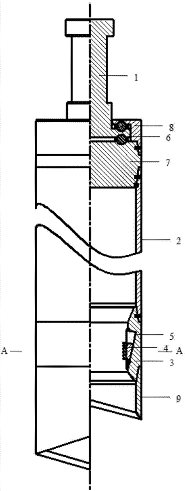
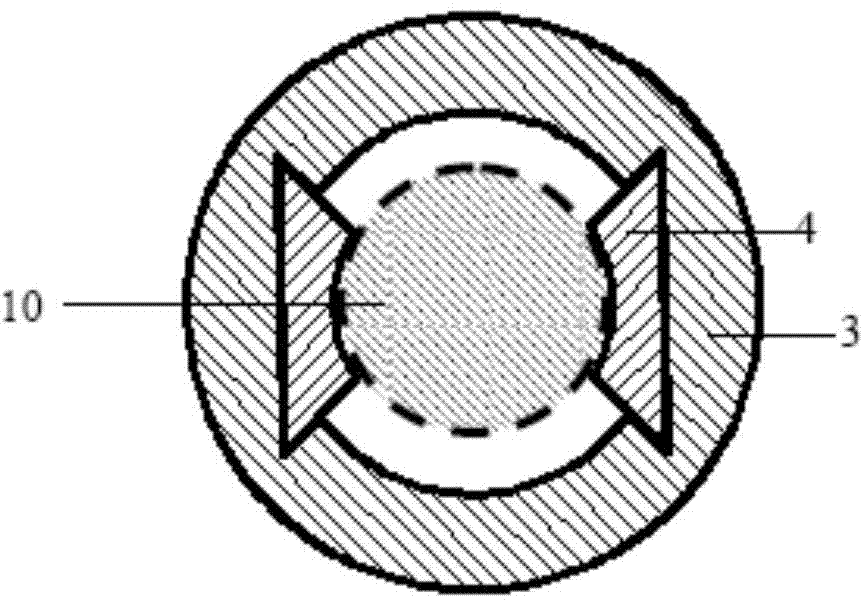
[0012] Depend on figure 1 , figure 2 It can be seen that the present invention consists of a lifting head 1 and a blowout prevention cylinder 2. The lower part of the blowout prevention cylinder 2 is a slip, and the slips include a slip seat 3 and a slip tooth 4. The inner pipe wall of the slip seat 3 has at least Two inverted tapered slots 5, the slip teeth 4 are placed in the slots 5, and a rotating bearing 6 is installed between the upper part of the blowout prevention cylinder 2 and the lifting head 1.
[0013] The lifting head 1 is a "convex" shape structure; the upper end surface of the blowout prevention cylinder 2 is provided with a hollow hole that fits with the lifting rod of the lifting head 1; the upper end of the blowout prevention cylinder 2 is lapped on the lifting head through a rotating bearing 6 1 on the lower deck.
[0014] The upper end of the blowout prevention cylinder 1 is fixedly equipped with a plug 7, and the upper part of the plug 7 is lapped on t...
PUM
 Abstract
Description
Claims
Application Information