Auxiliary suction pipe, suction structure, household appliance and dehumidifier

A suction pipe and piping technology, which is applied in the field of household appliances, can solve problems such as vibration noise, large pipes, and obvious problems, and achieve the effects of reducing stress and strain, reducing noise, and good release

Active Publication Date: 2015-04-08
GREE ELECTRIC APPLIANCES INC
View PDF11 Cites 2 Cited by
  • Summary
  • Abstract
  • Description
  • Claims
  • Application Information

AI Technical Summary

Problems solved by technology

[0004] The inventors found that there are at least the following problems in the prior art: the vibration source of the household dehumidifier mainly comes from the compressor of the dehumidifier, and is transmitted to the outside through the foot of the compressor and the piping pipeline. The vibration of the compressor and the influence of the refrigerant flow make it in a forced vibration state, resulting in obvious vibration and noise
Specifically, after the compressor is installed in the dehumidifier, the suction pipeline of the compressor is limited by the small space, and the layout of the pipeline is relatively difficult. The force received inside the pipeline cannot be released effectively and reasonably, so the vibration of the pipeline is aggravated, and at the same time, vibration noise is generated, resulting in relatively large vibration and noise of the dehumidifier
The existing piping method leads to large vibration stress and strain of the pipeline. Generally, the maximum strain is over 280μ during start-up and shutdown, and the maximum strain during operation is above 60μ. The overall strain is high and extremely unstable, and there is a great risk of pipeline leakage
Moreover, the noise value and sound quality of the compressor piped by this method are generally poor, which cannot meet the requirements of contemporary people for dehumidifiers.

Method used


Image

  • Auxiliary suction pipe, suction structure, household appliance and dehumidifier
  • Auxiliary suction pipe, suction structure, household appliance and dehumidifier
  • Auxiliary suction pipe, suction structure, household appliance and dehumidifier

Examples


Embodiment Construction

[0032] Combine below Figure 1 to Figure 6 The technical solutions provided by the present invention are described in more detail, and the technical solutions obtained by replacing any technical means provided by the present invention or by combining any two or more technical means or technical features provided by the present invention with each other All should fall within the protection scope of the present invention.

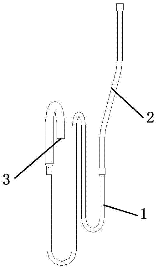
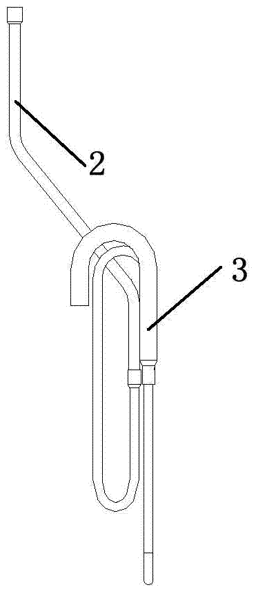
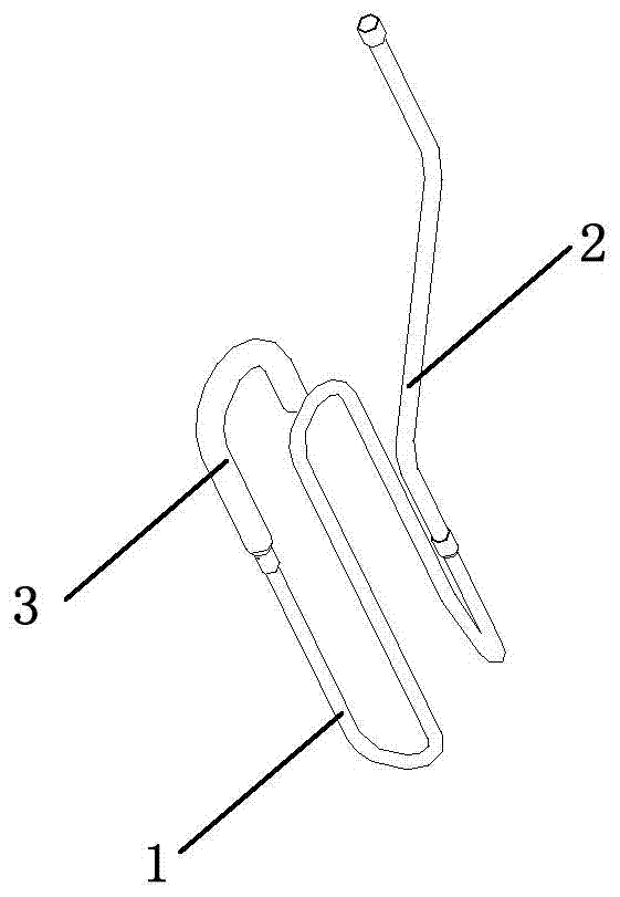
[0033] The embodiment of the present invention provides a suction piping pipeline, which includes a first suction pipe 1 and a connecting pipe 3. One end of the connecting pipe 3 is communicated with the other end of the first suction pipe 1, and the outside of the first suction pipe 1 is connected to the other end of the first suction pipe 1. The ratio of the diameter to the outer diameter of the connecting pipe 3 is less than 63%.

[0034] For example, if the connecting pipe 3 is a pipe with a diameter of 9.52, the outer diameter of the pipe used in the f...


PUM


Abstract

The invention discloses an auxiliary suction pipe, a suction structure, a household appliance and a dehumidifier for lowering noise produced by the auxiliary suction pipe and relates to the field of household appliances. The auxiliary suction pipe comprises a first suction pipe and a connecting pipe, one end of the connecting pipe is communicated with the other end of the first suction pipe, and the ratio between the outer diameter of the first suction pipe and the outer diameter of the connecting pipe is less than 63%. Different form the existing auxiliary suction pipe formed by pipes with the outer diameter more than 63% of the size of the connecting pipe, the auxiliary suction pipe applies the first suction pipe with small outer diameter, noise caused by vibration of the pipe is lowered by the aid of flexibility of the pipe, and noise of the complete appliance is lowered to the uttermost degree; meanwhile, pipe stress is released better, and stress-strain is lowered.

Description

technical field [0001] The invention relates to the field of household appliances, in particular to a suction piping pipeline, a suction structure, a household appliance and a dehumidifier. Background technique [0002] With the improvement of life quality, household dehumidifiers with small size and compact structure have gradually entered people's lives, and the public's requirements for the performance indicators of dehumidifiers are also getting higher and higher. The noise of a household dehumidifier directly affects the user's experience. The abnormal noise of household dehumidifiers is mainly caused by the joint action of compressors, fans, piping pipes and sheet metal parts, especially the noise caused by the vibration of piping pipes, which contributes greatly to the vibration and noise of the whole machine, and the Large vibration also easily leads to fatigue fracture of the piping. [0003] At present, most of the existing household 40L dehumidifier suction pipe...

Claims


Application Information

Patent Timeline
Patent Type & Authority Applications(China)
IPC IPC(8): F24F13/02F24F13/24F16L33/02
CPCF24F13/0209F24F13/0218F24F13/24F24F2013/247
Inventor 王美张辉叶务占金海元符龙
Owner GREE ELECTRIC APPLIANCES INC
Why Eureka
Try Eureka