An Improved Vapor Compression-Jet Coupling Refrigeration System

A refrigeration system and steam technology, used in refrigerators, refrigeration components, refrigeration and liquefaction, etc., can solve problems such as poor adaptability to changing conditions, small ejector ejection ratio, and system performance degradation, to ensure stable work, improve Energy efficiency, small size effect

Inactive Publication Date: 2016-08-24
SHANDONG UNIV
View PDF6 Cites 0 Cited by
  • Summary
  • Abstract
  • Description
  • Claims
  • Application Information

AI Technical Summary

Problems solved by technology

In the compressor-injection coupling system, the exhaust gas from the compressor enters the injector directly, the temperature is high, and the specific volume is large, which will lead to a small injection ratio of the injector and a large amount of working fluid required, resulting in a decrease in system performance and COP reduce
According to existing research, the working pressure of the ejector is limited by the outlet back pressure, that is, the condenser pressure, and has poor adaptability to changing working conditions

Method used


Image

  • An Improved Vapor Compression-Jet Coupling Refrigeration System

Examples


Embodiment Construction

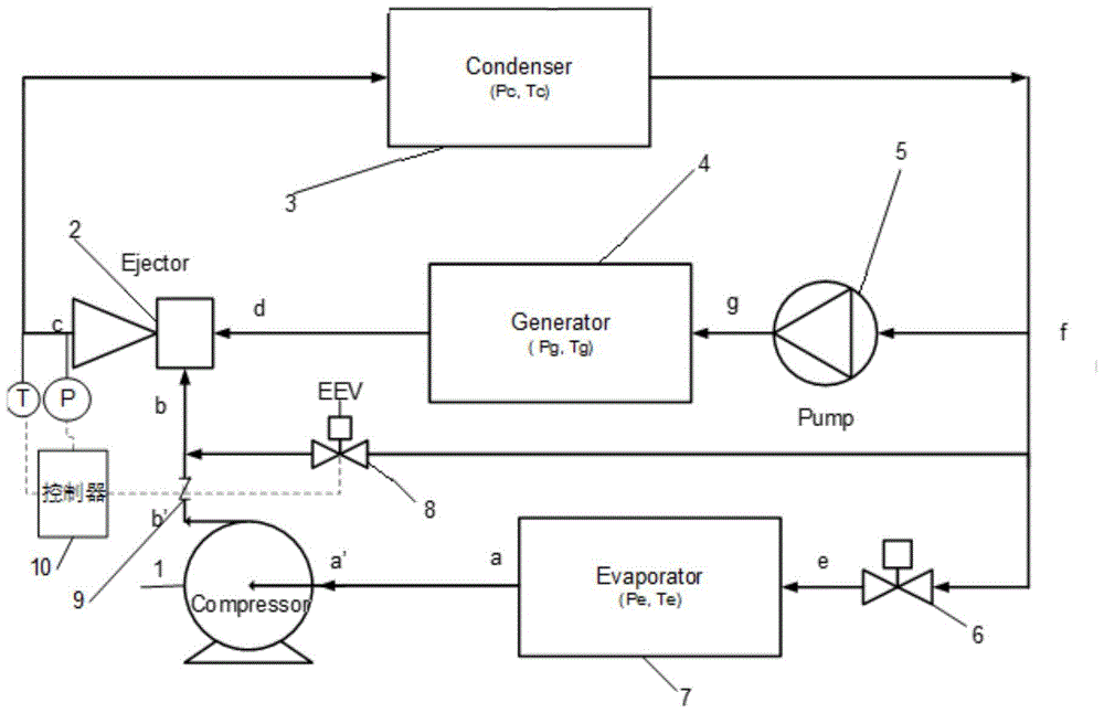
[0022] The present invention is described in detail below in conjunction with accompanying drawing:

[0023] Such as figure 1 As shown, an improved vapor compression-jet coupled refrigeration system includes a condenser 3, and the output of the condenser 3 is divided into three circuits, one of which is connected to the input end of the pump 5, and the other is connected to one end of the throttle valve 8, the first The three-way is connected to one end of the throttle valve 6, the output end of the pump 5 is connected to the input end of the generator 4, and the output end of the generator 4 is connected to the input end of the condenser 3 through the ejector 2, and the throttle valve The other end of 8 is connected with the input end of ejector 2, and the other end of throttle valve 6 is connected with evaporator 7, compressor 1 and ejector 2 in sequence.

[0024] The present invention proposes an improved vapor compression-jet coupled refrigeration system, whose main featu...


PUM


Abstract

The invention discloses an improved vapor compression-jet coupled refrigeration system, which includes a condenser. The output of the condenser is divided into three paths, one path is connected with the input end of the pump, the other path is connected with one end of the second throttle valve, and the third path is connected with the input end of the pump. The road is connected to one end of the first throttle valve, the output end of the pump is connected to the input end of the generator, the output end of the generator is connected to the input end of the condenser through the ejector, and the other end of the second throttle valve It is connected with the input end of the ejector, and the other end of the first throttle valve is connected with the evaporator, the compressor and the ejector in turn. In the present invention, a branch is drawn from the condenser, and the branch pipeline is connected with the outlet pipeline of the compressor through the second throttle valve, and the gas-liquid two-phase fluid is mixed with the gas compressed by the compressor after condensation and throttling, and is cooled , and then sucked into the injector. The method can improve the working condition of the injector and increase the injection ratio of the injector.

Description

technical field [0001] The present invention relates to an improved vapor compression-jet coupled refrigeration system. Background technique [0002] The vapor compression-jet coupled refrigeration cycle can make full use of waste heat, solar energy, low-grade heat sources, etc. to replace part of the compression work, thereby saving mechanical energy consumption and improving energy utilization efficiency. [0003] The existing vapor compression-jet coupled refrigeration cycle has disadvantages such as low efficiency and small injection ratio of the ejector. This paper proposes a method that can improve system efficiency and increase the injection ratio of the ejector. [0004] Application number: 2005101110230, which proposes an "automobile air-conditioning refrigeration system driven by a compressor and exhaust waste heat", which uses the exhaust heat of automobile exhaust to drive the automobile air conditioner, and the insufficient part is supplemented by a compression ...

Claims


Application Information

Patent Timeline
Patent Type & Authority Patents(China)
IPC IPC(8): F25B25/00F25B41/06F25B41/31
CPCF25B25/00F25B41/30
Inventor 赵红霞王雷匙明申张科
Owner SHANDONG UNIV
Why Eureka
Try Eureka