Device for measuring diffusion coefficient of CO2 diffusing from aqueous phase to oil phase and operating method thereof
A diffusion device and diffusion coefficient technology, applied in measuring devices, instruments, scientific instruments, etc., can solve problems such as the inability to measure the diffusion coefficient and the difference in density of oil, gas and water
- Summary
- Abstract
- Description
- Claims
- Application Information
AI Technical Summary
Problems solved by technology
Method used
Image
Examples
Embodiment 1
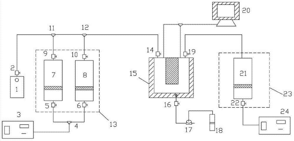
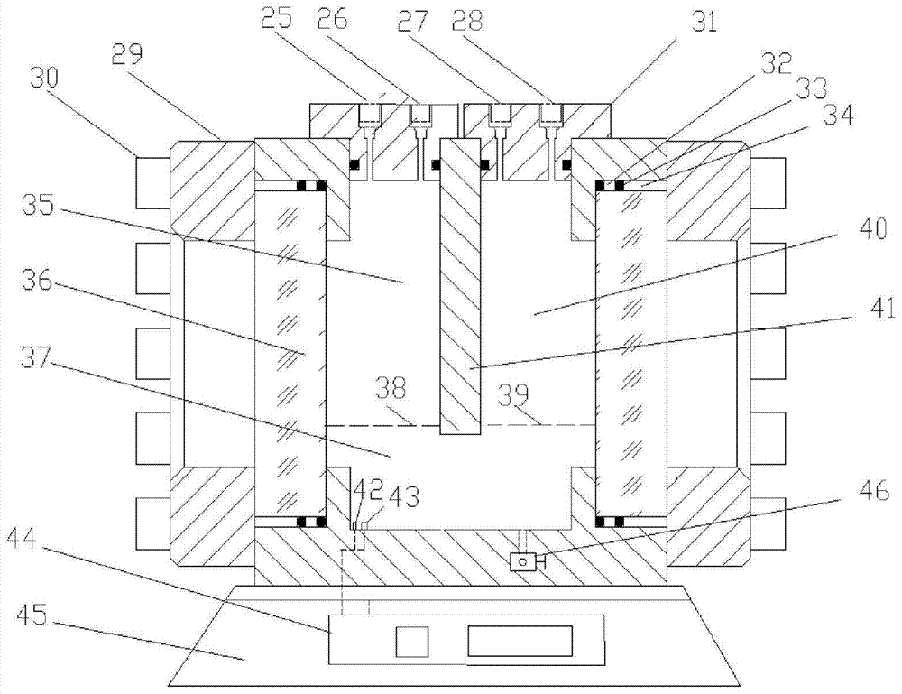
[0097] A measure of CO 2 The device for the diffusion coefficient in the process of diffusion from the water phase to the oil phase, including the CO pipes connected vertically and side by side in sequence 2 Gas source, distilled water source, U-shaped high-temperature and high-pressure visible diffusion device 15, and crude oil source, and a steel body partition 41 is vertically arranged in the U-shaped high-temperature and high-pressure visible diffusion device 15, and the steel body partition 41 divides the The U-shaped high-temperature, high-pressure visible diffusion device 15 is divided into a left space 35 and a right-side space 40 connected at the bottom, and the bottom of the U-shaped high-temperature, high-pressure visible diffusion device 15 is provided with a temperature measuring point 42, a pressure measuring point 43, Lower exit 46, the CO 2 The gas source and the distilled water source are respectively communicated with the left side space 35 through pipelines...
Embodiment 2
[0100] According to the device described in Embodiment 1, the difference is that a base 45 is provided at the bottom of the U-shaped high temperature and high pressure visible diffusion device 15 , and the temperature control system 44 is provided on the base 45 .
Embodiment 3
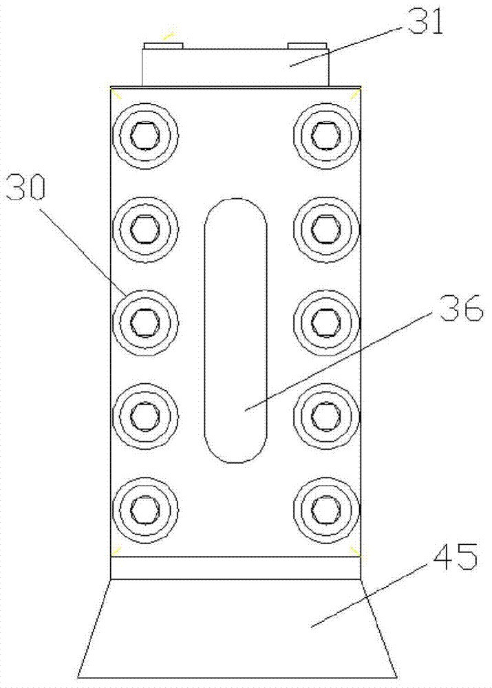
[0102] According to the device described in embodiment 1 or 2, the difference is that the two sides of the U-shaped high-temperature and high-pressure visible diffusion device 15 are provided with a pressure-bearing visible glass 36 and a stainless and corrosion-resistant steel body 29. The pressure-bearing visible glass 36 is embedded in the stainless and corrosion-resistant steel body 29, and the middle pressure pad 32, O-ring 33, and upper pressure pad 34 seal the pressure-bearing visible glass 36 and the stainless and corrosion-resistant steel body 29. The annular gap between the steel bodies 29; the stainless and corrosion-resistant steel body 29 has a temperature resistance of 150° C. and a pressure resistance of 32 MPa; the pressure resistance of the middle pressure pad 32 , O-ring 33 and upper pressure pad 34 is 25 MPa.
[0103] The advantage of the design here is that the pressure-bearing sight glass 36 can objectively and truly observe the change of the liquid level d...
PUM
 Abstract
Description
Claims
Application Information
 - R&D
- Intellectual Property
- Life Sciences
- Materials
- Tech Scout
- Unparalleled Data Quality
- Higher Quality Content
- 60% Fewer Hallucinations
Browse by: Latest US Patents, China's latest patents, Technical Efficacy Thesaurus, Application Domain, Technology Topic, Popular Technical Reports.
© 2025 PatSnap. All rights reserved.Legal|Privacy policy|Modern Slavery Act Transparency Statement|Sitemap|About US| Contact US: help@patsnap.com


