Dynamic fatigue evolution test method for rubber and fiber cord thread bonding

A technology of dynamic fatigue and testing methods, applied in measuring devices, instruments, and mechanical devices, etc., can solve the problems of inability to predict tire life, no reports on data, and dynamic fatigue of bonding, achieving reliable data, broad application prospects, good reproducibility

Inactive Publication Date: 2015-04-08
QINGDAO UNIV OF SCI & TECH
View PDF6 Cites 11 Cited by
  • Summary
  • Abstract
  • Description
  • Claims
  • Application Information

AI Technical Summary

Problems solved by technology

The pure static method or the "H" pull-out force method after dynamic fatigue obviously cannot reflect the continuous evolution process of the bond under these stresses and strains, so it is impossible to make a reasonable prediction of the life of t

Method used


Image

  • Dynamic fatigue evolution test method for rubber and fiber cord thread bonding
  • Dynamic fatigue evolution test method for rubber and fiber cord thread bonding
  • Dynamic fatigue evolution test method for rubber and fiber cord thread bonding

Examples


preparation example Construction

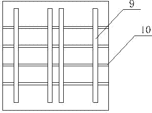
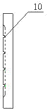
[0040] Preparation of rubber / fiber cord vulcanization specimens: the vulcanization mold used is as figure 1 and figure 2 shown. First place the four strips respectively in the mold cavity shown in the mold with the working side facing up. Then insert the fiber cord into the cord groove, so that the knotted end is stuck in one end of the cord groove, and the other end is naturally tightened by the weight. Then place the other four strips on top of the bottom strip, with the working side facing down. Finally, cover the upper mold and place it on a flat vulcanizing machine for vulcanization.

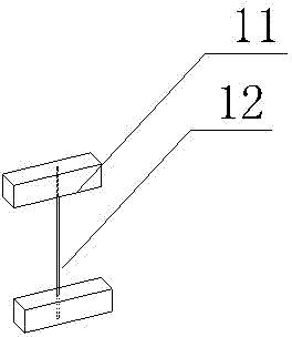
[0041] Rubber / fiber cord fatigue sample preparation: cut the sample with scissors to make an "I"-shaped sample, such as image 3 shown. The sample is buried between two rubber blocks 11 with a length of about 25 mm at both ends of a single fiber cord 12, and the remaining rubber is carefully cut off with scissors, taking care not to damage the fiber cord.

[0042] Dynamic fatigue tes...

Embodiment 1

[0047] Example 1: Dynamic Fatigue Continuous Evolution Strain Control of Rubber and Fiber Cord Bonding

[0048] 1. Preparation before vulcanization:

[0049] Weighing: according to the formula NR 90phr, SBR 10phr, zinc oxide 3phr, stearic acid 2phr, antioxidant RD 2phr, carbon black N330 5phr, carbon black N660 30phr, aromatic oil 500 3phr, binder A 0.8phr, binder RE 0.6phr, DM 1.2phr, TMTD 0.03phr, insoluble sulfur 2.5phr Weigh raw materials;

[0050] Rubber mixing: Add the above raw materials into the internal mixer for rubber mixing, set the initial speed at 60rpm, and the initial temperature at 60°C. First add NR and SBR, and after mixing for 1 minute, add zinc oxide, stearic acid, anti-aging agent RD and adhesive Agent RE, add half of carbon black and aromatic oil when the torque level is about 2 minutes, add the other half of carbon black and aromatic oil at 3.5 minutes, open the top bolt to clean once at 4.5 minutes, and remove glue after 8 minutes. After the rubber m...

Embodiment 2

[0059] Example 2 Rubber and Fiber Cord Bonding Dynamic Fatigue Continuous Evolution Stress Control

[0060] Other steps adopted in the second embodiment are the same as those in the first embodiment, except that the clamps are different and step 4 is different. In step 4, instead of setting the maximum tensile displacement, the maximum tensile stress of the upper and lower clamps is set to 22N by computer for dynamic testing. In the screening data, the displacement value when the tension value is about 22N is plotted against time, and the following can be obtained: Figure 8 curve. The dynamic evolution of bonding over time can also be seen.

[0061] The difference between the clamp and the first embodiment is that the others are the same, except that the rotating adjustment handle 5 includes an elliptical adjusting rod located above the limit plate 6, and a connecting shaft is arranged at the center of one end of the elliptical adjusting rod, and the connecting shaft passes...


PUM

PropertyMeasurementUnit
Thicknessaaaaaaaaaa
Sizeaaaaaaaaaa

Abstract

The invention discloses a dynamic fatigue evolution test method for rubber and fiber cord thread bonding, by means of connecting a fixture with an MTS elastomer test system, the method realizes simulation of continuous evolution process of bonding failure of rubber and a fiber cord thread under various conditions of use in multiple modes such as constant stress, constant strain as well as alternating load and alternating frequency. The beneficial effects of the method are that: the method is simple to operate, the data is reliable, the reproducibility is high, the test process has time continuity, so the method can better simulate the evolution process of bonding fatigue rupture of multiple kinds of rubber and various fiber cord thread composite materials under the condition of real stress, and has important guiding significance for predicting the service life of rubber products,thereby having a broad application prospect.

Description

technical field [0001] The invention relates to the technical field of rubber and fiber cord composite materials, in particular to a dynamic fatigue evolution test method for rubber and fiber cord bonding. Background technique [0002] With the popularization of automobiles and the improvement of modernization level, people's requirements for tire performance are becoming more and more stringent. Among all performances, the durability and service life of tires are of great concern to the tire industry and consumers. In tires, fiber cords are widely used as a skeleton material in carcass structures. As two materials with completely different properties, their adhesion is directly related to the safety of the tire. Therefore, in order to ensure that high-quality tires are put into use, the tire factory must test the bonding of rubber and fiber cords. [0003] At present, the most simple and commonly used method to measure the adhesion between rubber and fiber cord is the ...

Claims


Application Information

Patent Timeline
IPC IPC(8): G01N19/04
Inventor 史新妍廉成波商元元
Owner QINGDAO UNIV OF SCI & TECH
Why Eureka
Try Eureka