
Method and system for recognizing lightning strike failure and lightning strike failure type of power transmission line

A technology for lightning strike faults and power transmission lines, which can be applied to fault locations, information technology support systems, and power measurement, and can solve problems such as poor reliability

Active Publication Date: 2015-04-08
STATE GRID CORP OF CHINA +2
View PDF5 Cites 8 Cited by
  • Summary
  • Abstract
  • Description
  • Claims
  • Application Information

AI Technical Summary

Problems solved by technology

After the line is put into operation, the distinction between shielding and counterattack faults is mostly based on the magnitude of the lightning current combined with the insulator flashover situation and is judged by the experience of the engineers, which is highly subjective and poor in credibility.

Method used


Image

  • Method and system for recognizing lightning strike failure and lightning strike failure type of power transmission line
  • Method and system for recognizing lightning strike failure and lightning strike failure type of power transmission line
  • Method and system for recognizing lightning strike failure and lightning strike failure type of power transmission line

Examples


Embodiment 1

[0101] The 500kV double-circuit line A and B on the same tower has a total length of 186.642 kilometers. A set of fault detection devices is installed on the No. 267 tower at the 125.37km point at the head end of the line.

[0102] One day the fault tripped, and the fault detection device installed on the No. 267 tower detected the fault traveling wave current, and its signal was as follows: Figure 4 As shown, wave header information is shown in Table 2.

[0103] Table 2 Fault traveling wave header information

[0104]

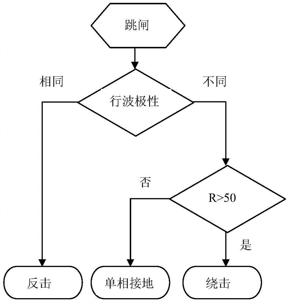
[0105] It can be seen from Table 2 that the polarity of phase B is opposite to AC, and the line can be preliminarily determined to be a shielding or non-lightning fault. The current change rate R of phase B of the fault phase is 7.175, which is less than 50, so it is judged as a single-phase ground fault.

[0106] After the inspection, it was found that the right ground wire of N35-N36 of the above-mentioned 500kV A line was broken, and one end of the bro...

Embodiment 2

[0108] The total length of the 500kV line is 148.440km. A phase fault tripped on a certain day. The fault detection device detects the fault traveling wave current, and its signal is as follows: Figure 5 As shown, wave header information is shown in Table 3.

[0109] Table 3 Fault traveling wave header information

[0110]

[0111] It can be seen from Table 3 that the polarity of phase A is opposite to that of BC, and the line can be preliminarily determined to be a shielding or non-lightning fault. The current change rate R of phase A of the fault phase is 77, which is greater than 50, so it is judged as a shielding fault.

[0112] After the inspection, it was found that there were traces of flashover discharge on the A-phase conductor and voltage equalizing shielding ring of a tower of the above-mentioned 500kV line. The inspection facts are consistent with the judgment conclusion of this embodiment.


PUM


Abstract

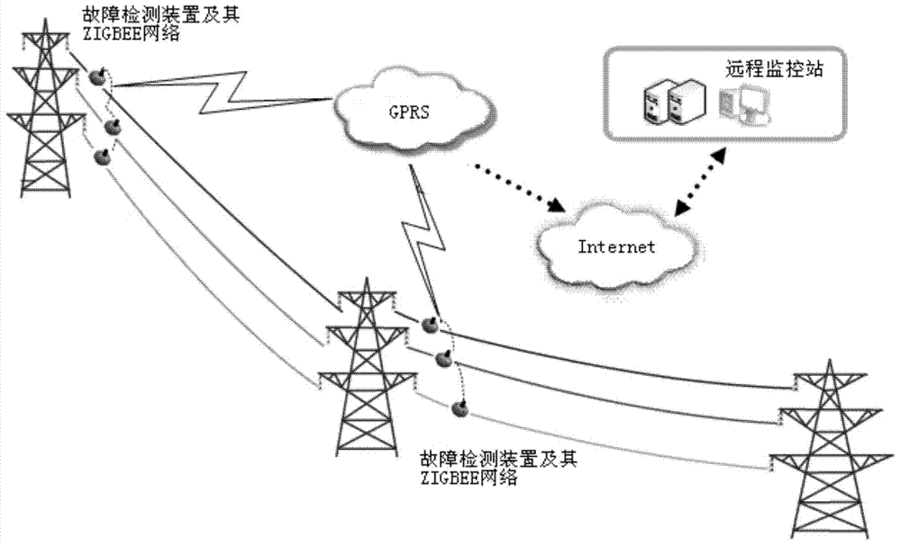
The invention discloses a method for recognizing the lightning strike fault and the lightning strike fault type of a power transmission line. The method comprises the steps of immediately judging the polarities of ABC three-phase current traveling waves after the power transmission line is subjected to single-phase fault tripping; judging that the power transmission line is subjected to the lightning strike fault and the fault type is counterstrike if the polarities are totally the same; executing a next step if the polarities are not totally the same; determining a current change rate R of a fault phase, and judging that the power transmission line is subjected to the lightning strike fault and the fault type is shielding failure if R is greater than a threshold value; judging that the power transmission line is subjected to a single-phase ground fault if R is not greater than the threshold value. The invention also discloses a system for recognizing the lightning strike fault and the lightning strike fault type of the power transmission line. The system comprises at least one group of fault detection devices, a wireless communication system and a remote monitoring station, wherein the fault detection devices, the wireless communication system and the remote monitoring station are sequentially connected, and the remote monitoring station adopts the method for judging the fault type of the power transmission line.

Description

technical field [0001] The invention relates to the field of fault identification of transmission lines, in particular to a method and system for identifying lightning strike faults of transmission lines. Background technique [0002] Operational experience at home and abroad shows that direct lightning strikes are the main cause of high-voltage transmission line tripping, which can be divided into two types: shielding strikes and counterattacks. The phenomenon that lightning bypasses the lightning conductor and directly strikes the conductor is called shielding; when lightning strikes the lightning conductor or the top of the tower, if the grounding resistance is large, the potential at the top of the tower may be much higher than that of the conductor, which is caused by this voltage The insulator string flashover is called counterattack. The mechanism and process of shielding and counterattack are different, and the protective measures are also different. The shielding ...

Claims


Application Information

Patent Timeline
IPC IPC(8): G01R31/08G01R31/02
CPCY04S10/52
Inventor 洪军刘亚东马欣朱清孔平樊秀娟张勇刘仰安仵宗生吕修峰
Owner STATE GRID CORP OF CHINA
Learn More